
Optical disc device

a technology of optical discs and optical discs, applied in the field of optical disc devices, can solve the problems of rapid progression of optical disc deterioration, and continuous standby state servo misalignment, so as to reduce or prevent deterioration of optical discs

Inactive Publication Date: 2014-10-02
FUNAI ELECTRIC CO LTD
View PDF1 Cites 0 Cited by
  • Summary
  • Abstract
  • Description
  • Claims
  • Application Information

AI Technical Summary

Benefits of technology

This patent is about an optical disc device that prevents problems with the discs when they are not being used. It is designed to reduce or prevent servo misalignment and deterioration of the discs when they are in a standby state.

Problems solved by technology

However, irradiation of the optical disc with a high-frequency laser leads to the deterioration of optical discs.
When the optical disc device is paused during disc access and goes on standby for long periods of time, in particular, there is a problem in that the high-frequency laser is constantly shining and causes a rapid progression in optical disc deterioration.
Therefore, there is a possibility of servo misalignment occurring continuously in standby states (i.e., in idle mode).

Method used


Image

  • Optical disc device
  • Optical disc device
  • Optical disc device

Examples


Embodiment Construction

[0037]Preferred embodiments of the present invention will be described below with reference to the drawings. Note that the preferred embodiments described and shown herein are just examples, and the present invention is in no way limited to the preferred embodiments described and shown herein.

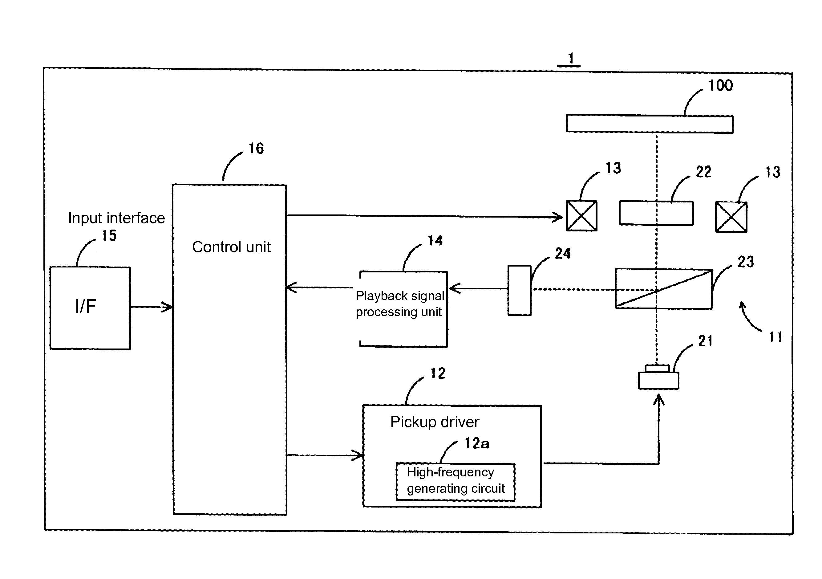
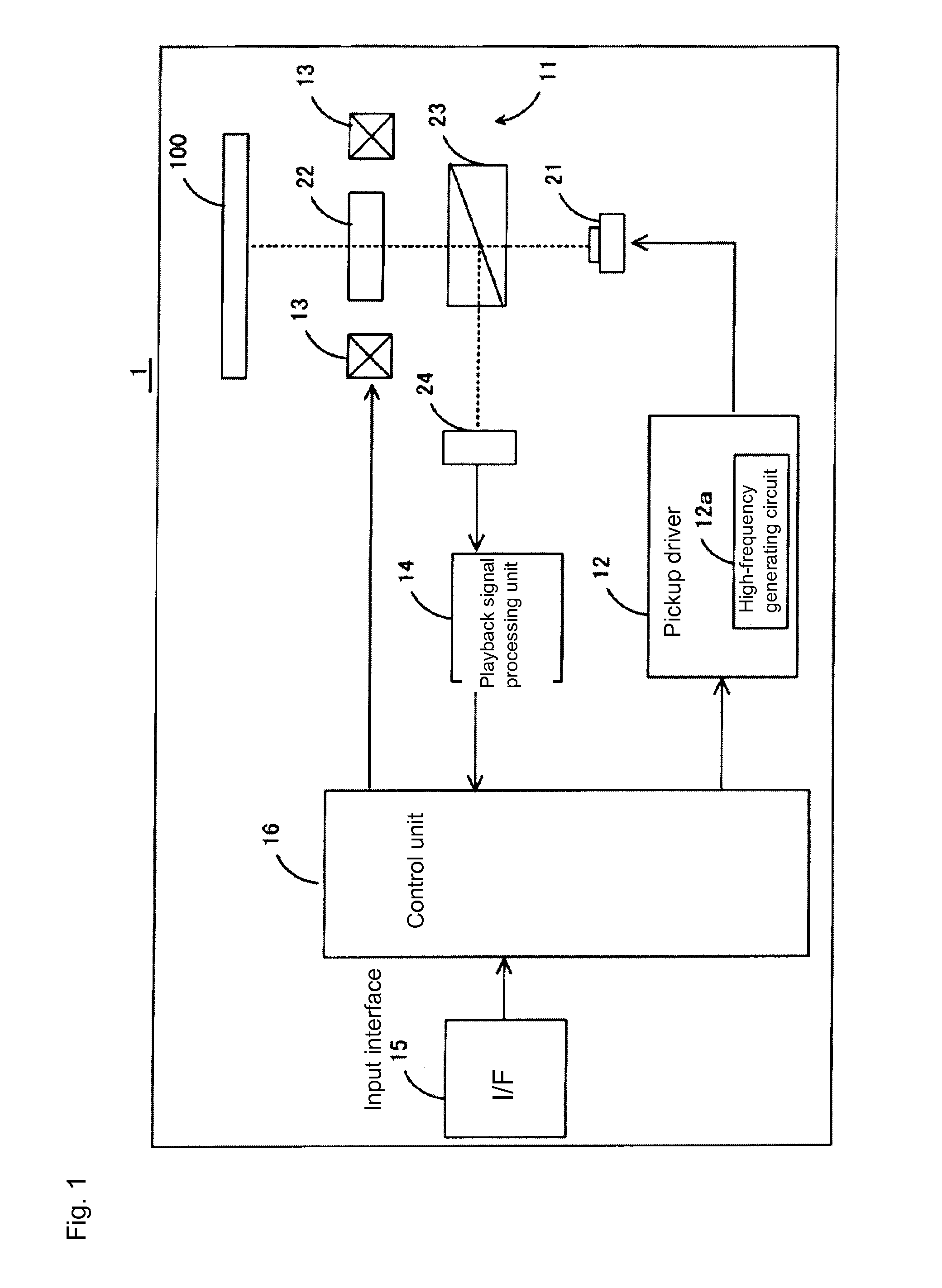
[0038]FIG. 1 is a configuration diagram showing an optical disc device 1 according to a preferred embodiment of the present invention. The optical disc device 1 can record data pertaining to television broadcasting on an optical disc 100 such as a Blu-ray disc, for example. Furthermore, the optical disc device 1 can play back data recorded on the optical disc 100 and output it to an external device (such as an LCD monitor; not shown) connected to the optical disc device 1.

[0039]As shown in FIG. 1, the optical disc device 1 is equipped with an optical pickup unit 11, a pickup driver 12, a position control unit 13, a playback signal processing unit 14, an input interface 15, and a control unit 16...


PUM

PropertyMeasurementUnit
frequencyaaaaaaaaaa
lengthaaaaaaaaaa
durabilityaaaaaaaaaa

Abstract

An optical disc device includes an optical pickup unit including a semiconductor laser that shines a laser light, a light-receiving unit that receives the return light of the laser light, a high-frequency generating circuit that generates high-frequency signals, a pickup driver that generates a drive signal that drives the semiconductor laser based on the high-frequency signal, a control unit that controls the high-frequency generating circuit such that, in states in which playback of the optical disc is halted while irradiation with the laser light is being performed, the signal level of the high-frequency signal to be superimposed is set at a first signal level other than zero so as to be smaller than in states in which the playback is performed.

Description

BACKGROUND OF THE INVENTION[0001]1. Field of the Invention[0002]The present invention relates to an optical disc device which plays back optical discs.[0003]2. Description of the Related Art[0004]Optical discs such as compact discs (CDs), digital versatile discs (DVDs), and Blu-Ray discs (BDs, registered trademark) have come to be widely used in recent years. Furthermore, optical disc devices have been put into practical use as devices for reading, recording, and playing back information recorded on optical discs, such as audio data and image data. Some examples of widely known optical disc devices are CD players, DVD players, BD players, and CD-ROM drives connected to personal computers.[0005]Optical disc devices are equipped with optical pickups for irradiating optical discs with laser light and reading data from them. Optical pickups have laser diodes that shine laser light onto the data recording surface of optical discs affixed to turntables on which they rotate.[0006]Optical p...

Claims


Application Information

Patent Timeline
Patent Type & Authority Applications(United States)
IPC IPC(8): G11B7/1263
CPCG11B7/1263G11B7/127
Inventor FUJITA, SHINJI
Owner FUNAI ELECTRIC CO LTD
Learn More