Focusing control device, focusing control method, and program

a focusing control and control method technology, applied in the field of focusing control devices, can solve the problems of blurred captured images, image deviation of subjects within distance measurement areas, etc., and achieve the effect of improving the specification accuracy of focusing positions

Active Publication Date: 2022-05-17
FUJIFILM CORP
View PDF23 Cites 0 Cited by
  • Summary
  • Abstract
  • Description
  • Claims
  • Application Information

AI Technical Summary

Benefits of technology

[0005]The present disclosure has been made in consideration of the above circumstances, and an object of the present disclosure is to provide a focusing control device, a focusing control method, and a program capable of improving specification accuracy of a focusing position even though a position of an image of a subject changes according to a change of an image magnification of a focus lens.
[0016]Accordingly, according to the present disclosure, even though the position of the image of the subject changes according to the change of the image magnification of the focus lens it is possible to improve the specification accuracy of the focusing position.

Problems solved by technology

However, in the technology disclosed in JP2013-238746A, since a position of the image of the subject changes according to a change of an image magnification of the focus lens as the focus lens moves along an optical axis direction, the image of the subject may deviate within the distance measurement area.
In a case where the autofocus is performed by using a result obtained by performing peak search of a contrast value for the image within the distance measurement area and the image of the subject deviates from within the distance measurement area, a proper focusing state is not achieved, and thus, there is a problem that the captured image is blurred.

Method used


Image

  • Focusing control device, focusing control method, and program
  • Focusing control device, focusing control method, and program
  • Focusing control device, focusing control method, and program

Examples


first embodiment

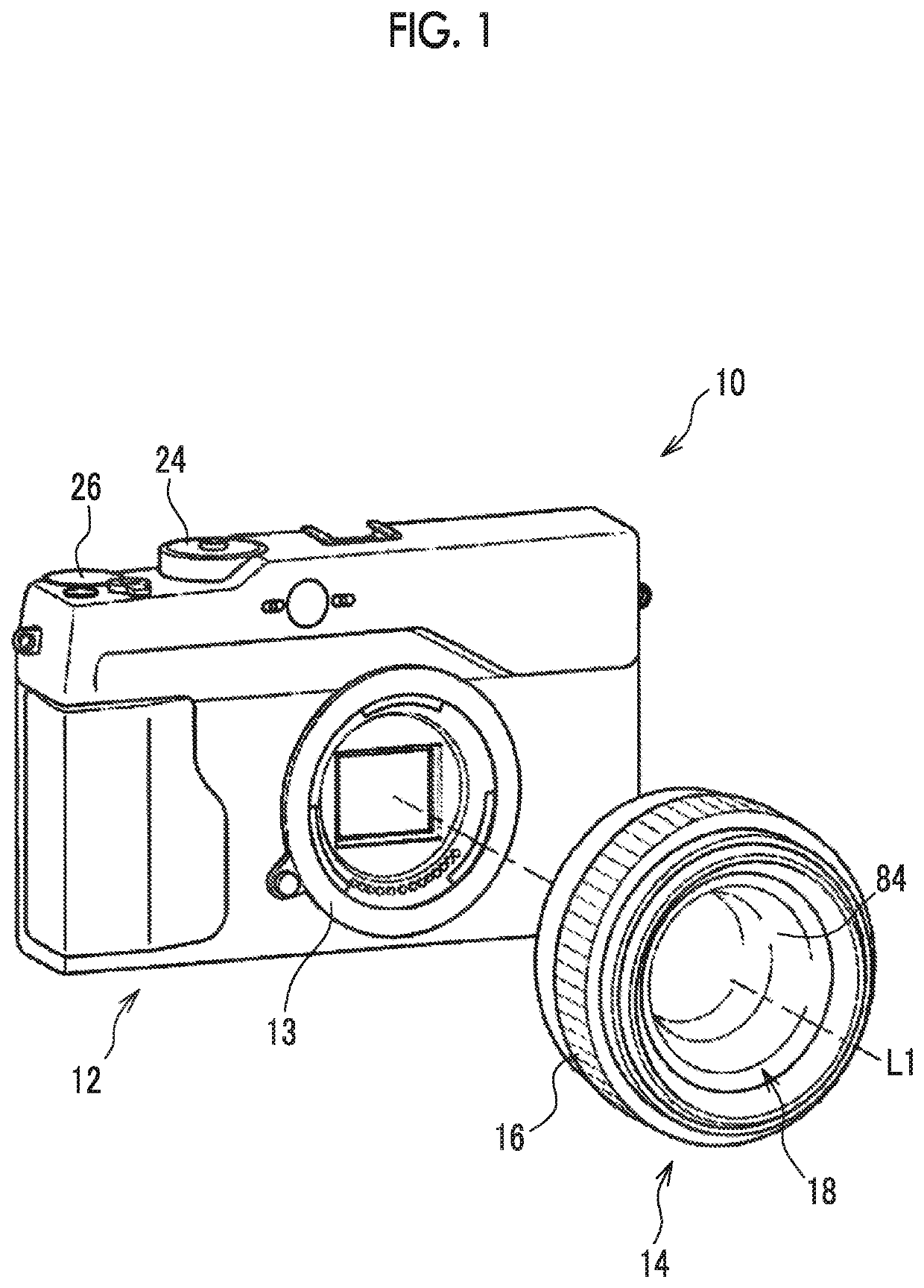
[0043]First, an example of a configuration of an imaging device 10 according to the present embodiment will be described. For example, as shown in FIG. 1, the imaging device 10 of the present embodiment is a lens-interchangeable digital camera, and includes an imaging device main body 12 and an imaging lens 14.

[0044]The imaging lens 14 is exchangeably attached to the imaging device main body 12. A focus ring 16 used in a manual focus mode is provided at a lens barrel of the imaging lens 14. The imaging lens 14 includes a lens unit 18.

[0045]The lens unit 18 is a combination lens in which a plurality of lenses including a focus lens 84 is combined. The focus lens 84 moves along a direction of an optical axis L1 as the focus ring 16 is manually rotated. The focus lens 84 is stopped at a focusing position corresponding to a subject distance. Subject light which is reflected light indicating a subject is transmitted through the lens unit 18 including the focus lens 84, and an image is fo...

second embodiment

[0105]Hereinafter, a second embodiment will be described in detail. In the present embodiment, the same configurations and functions as those described in the first embodiment will be assigned by the same references, and detailed description thereof will be omitted.

[0106]The configuration of the imaging device 10 of the present embodiment is the same as the configuration of the imaging device 10 of the first embodiment (see FIGS. 1 to 4), and thus, description thereof will be omitted. The CPU 74 of the present embodiment is an example of an instruction unit of the present disclosure.

[0107]Meanwhile, the function of the imaging device 10 of the present embodiment is different in a part of the focusing control processing. In the focusing control processing, the subject may move during the operation of the peak detection. In a case where the subject moves, the position of the image 154 of the subject in the captured image 150 also changes. As a method corresponding to such a case, ther...

third embodiment

[0114]Hereinafter, a third embodiment will be described in detail. In the present embodiment, the same configurations and functions as those described in the first and second embodiments will be assigned by the same references, and detailed description thereof will be omitted.

[0115]The configuration of the imaging device 10 of the present embodiment is the same as the configuration of the imaging device 10 of the first embodiment (see FIGS. 1 to 4), and thus, description thereof will be omitted.

[0116]It has been described in the second embodiment in which the subject tracking mode is executed by the CPU 74 in a case where the acceptance device 62 accepts the instruction to execute the subject tracking mode from the user. In the present embodiment, a mode in which the subject tracking mode can be automatically executed even though the acceptance device 62 does not accept the instruction to execute the subject tracking mode from the user will be described.

[0117]In a case where the sub...


PUM


Abstract

A focusing control device that moves a position of a focus lens included in an imaging lens along an optical axis direction. The device comprises a processor configured to execute a process. The process comprises receiving an input of a captured image obtained by imaging an optical image passed through the imaging lens including the focus lens; performing one processing of first processing that includes deriving a contrast value of an image within a distance measurement area which changes according to the movement of the position of the focus lens for each of a plurality of the distance measurement areas, specifying a peak of the contrast value based on the contrast value for each of the plurality of distance measurement areas, and specifying, as a focusing position, the position of the focus lens corresponding to the specified peak of the contrast value, or second processing that includes specifying the peak of the contrast value based on an added value obtained by adding the contrast values derived from the plurality of distance measurement areas and specifying, as the focusing position, the position of the focus lens corresponding to the specified peak of the contrast value; performing control such that the one processing is switched according to an amount of change of a position of an image of a subject corresponding to a change of an image magnification of the imaging lens, and moving the focus lens to the specified focusing position.

Description

CROSS-REFERENCE TO RELATED APPLICATIONS[0001]This application is a continuation application of International Application No. PCT / JP2018 / 045768, filed Dec. 12, 2018, the disclosure of which is incorporated herein by reference in its entirety. Further, this application claims priority from Japanese Patent Application No. 2018-068990 filed on Mar. 30, 2018, the disclosures of which are incorporated herein by reference in its entirety.BACKGROUND OF THE INVENTION1. Technical Field[0002]A technology of the present disclosure relates to a focusing control device, a focusing control method, and a program.2. Description of the Related Art[0003]In the related art, a technology of deciding a focusing position of a focus lens based on a peak of a contrast value detected from a change of a contrast value of an image within a distance measurement area provided within a captured image in an imaging device that performs autofocus by a so-called contrast autofocus (AF) method is disclosed (see, for ...

Claims


Application Information

Patent Timeline
Patent Type & Authority Patents(United States)
IPC IPC(8): H04N5/232G02B7/09G02B7/36
CPCH04N5/232123G02B7/09G02B7/36G03B13/36H04N23/663H04N23/675H04N23/673
Inventor TANAKA, KOICHIHAYASHI, KENKICHIUCHIDA, AKIHIROIZAWA, SEIICHIFUJIKI, SHINICHIRO
Owner FUJIFILM CORP
Why Eureka
Try Eureka