Template guidance system for a router

a template guide and router technology, applied in the direction of metal-working machine components, wood mortising machines, manufacturing tools, etc., can solve the problems of difficult to precisely control using conventional, manual operation, methods and commonly available jigs and templates, and the guide bearing of the pantorouter system is somewhat time-consuming, so as to reduce the scale of cutting movements, improve the accuracy, and improve the effect of accuracy

Active Publication Date: 2022-06-07
WOODCRAFT SOLUTIONS LLC
View PDF9 Cites 0 Cited by
  • Summary
  • Abstract
  • Description
  • Claims
  • Application Information

AI Technical Summary

Benefits of technology

[0009]A PantoRouter™-type system is advantageous over the prior art, since the aforementioned imperfections in a template are minimized by a reduction in scale of cutting movements, and hence such a system enables a cleaner and more precise cut. And a cleaner, more precise cut, results in a more pleasing, accurate, repeatable and durable resulting workpiece joinery.
[0010]The invention shown, described and claimed herein addresses the problems of prior art router template systems, and it contributes to a more accurate, efficient, repeatable, pleasing appearance, and faster cut on a workpiece, as well as safer operating environments for operators. The invention is preferably used with a pantographic-type router mount with a 2:1 mechanical advantage over the router, and this mechanical advantage gives the operator control and precision superior to any other manually-controlled means of operation.

Problems solved by technology

The bit 52 for such a router 49 typically spins at up to ˜24,000 RPM and is often difficult to precisely control using conventional, manually-operated, methods and commonly available jigs and templates.
This adjustment of the guide bearing of the PantoRouter system has been somewhat time-consuming and has required a moderate amount of trial and error to set the depth of the guide bearing to an appropriate depth.
This common method has required trial and error to find the desired fit each time a similar joint has been cut.
Of course, a downside of such a system has been wasted material, more time-consuming measuring, uncertainty in the process of cutting, and this has also resulted in a final product that has frequently not been as precise as would otherwise have been desirable.
This in turn has led to woodworking joints, for example, such as mortise and tenon, dovetail, and box joints, that have not been as durable and have not been as accurately-fitting as would otherwise have been desirable.
This in turn has provided a lower quality, less durable, or slower output in design and functionality than would otherwise have been desirable.

Method used


Image

  • Template guidance system for a router
  • Template guidance system for a router
  • Template guidance system for a router

Examples


Embodiment Construction

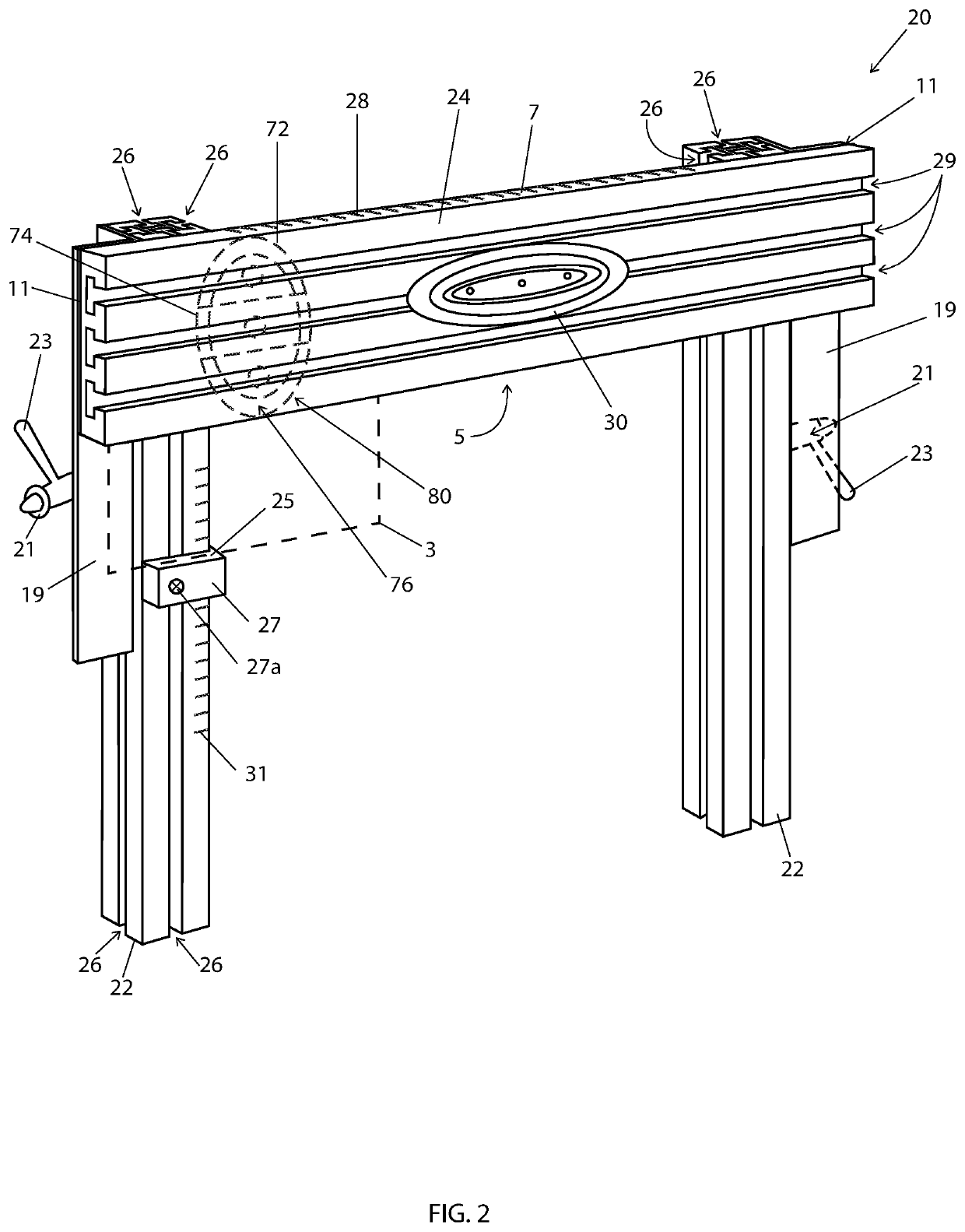
[0087]Referring specifically to FIGS. 2 and 3A-E, a template holder system 20 in accordance with one or more aspects of the disclosure preferably comprises a plurality of stands, or posts, 22 (preferably there are provided two such posts), and preferably a single cross member 24 interconnecting the two posts. The template holder system 20 may be comprised of a single post 22 and cross member 24, or more posts 22 may be employed as well, without departing from the true scope and spirit of the disclosure as claimed. However, it will be appreciated by those skilled in the art that two such posts is preferable from the standpoint of simplicity of use, rigidity and sturdiness of the resulting template guide system 20.

[0088]Each of the posts 22 of the template holder system 20 preferably has key slots, or grooves, 26 therein for facilitating alignment of the cross-member 24 thereon, for facilitating the adjustment of the template holder for use as described further hereafter for height ad...


PUM


Abstract

Tapered, stepped, or non-tapered router guide templates, optionally combined template holder system, and optional tapered or non-tapered guide bearing on a readily-locatable and lockable shaft, each template comprising: a base portion, a top portion, at least one of an exterior surface interconnecting the base portion and the top portion along an outer periphery of the template and an interior surface interconnecting the base portion and the top portion along an inner periphery of the template, wherein optionally one of the exterior surface and the interior surface may be continuously tapered between the base portion and the top portion, or stepped, and wherein the base portion is adapted for removable and adjustable interconnection with the template holder system.

Description

CROSS-REFERENCE TO RELATED APPLICATION[0001]The present patent application is a continuation-in-part patent application filed under 35 U.S.C. § 120 and claiming the priority and benefit of U.S. patent application Ser. No. 15 / 650,794, filed 14 Jul. 2017.FIELD OF INVENTION[0002]The present invention relates to a template-guided system for routers, and more particularly to a template-guided system for pantograph-type router systems comprising a readily adjustable template holder for holding a tapered template, or readily-adjustable tapered templates, the templates being readily adjustable on the template holder, together with an improved system and method for centering templates on the template holder, to facilitate efficient and highly accurate router cuts.BACKGROUND OF INVENTION[0003]As shown in FIGS. 1A-D, a router 10 (as shown in FIG. 5) has been commonly used with a pattern or jig 12, 14, 15 to follow a shape or a form. Some jigs have used a bit-mounted guide bearing 16 to follow ...

Claims


Application Information

Patent Timeline
Patent Type & Authority Patents(United States)
IPC IPC(8): B27F5/02B23Q3/00B27C5/10
CPCB23Q3/007B23Q3/002B27F5/02B23Q2735/004B27C5/10
Inventor SHELDON, DWIGHTSINGH, KULDEEP
Owner WOODCRAFT SOLUTIONS LLC
Why Eureka
Try Eureka