Electronic impression tray for obtaining dental information

a technology for dental information and impression trays, which is applied in the field of electronic impression trays for obtaining dental information, can solve the problems of complex manipulation and significant knowledg

Active Publication Date: 2022-06-14
DURET FRANCOIS +1
View PDF29 Cites 0 Cited by
  • Summary
  • Abstract
  • Description
  • Claims
  • Application Information

AI Technical Summary

Benefits of technology

[0019]It is also necessary to give the possibility of potentiating the optical impression in the mouth, which remains a penalizing act for the patient, by collecting at the same time, or in very close time, the shape of the dental surfaces and their shades, the gingival surfaces, the movements of the arches relative to one another and even, if time permits, the bone contours.
[0020]The object of the present invention is to meet all these needs, at a lower cost, by satisfying the patient by its comfort and speed, but also without requiring the practitioner to have too complex or too long training, while keeping a reasonable investment.
[0021]Thus, the electronic impression tray according to the invention can be used for obtaining three-dimensional and temporal measurements in dentistry, it consists of a device comprising optical measurement sensor systems, an electronic system which comprises a central management unit capable collecting, storing and ordering the data obtained by said sensors, the said sensors being distributed over all or part of said impression tray so as to allow an optical impression of all or part of a dental arch to be obtained with a single or multiple impressions, and it is characterized in that it consists of a part having the shape of all or part of a dental arch, and having a design that can change by virtue of its ability to deform and / or a structure formed by multiple elements that are hinged to one another and / or reversibly assembled and secured to one another, such as to provide the optimal shape.

Problems solved by technology

It turns out that the knowledge of bone contours, associated with the optical impression, requires complex manipulations and significant knowledge, which has led to the need to design a global impression system to respond to specifications.

Method used


Image

  • Electronic impression tray for obtaining dental information
  • Electronic impression tray for obtaining dental information
  • Electronic impression tray for obtaining dental information

Examples


Embodiment Construction

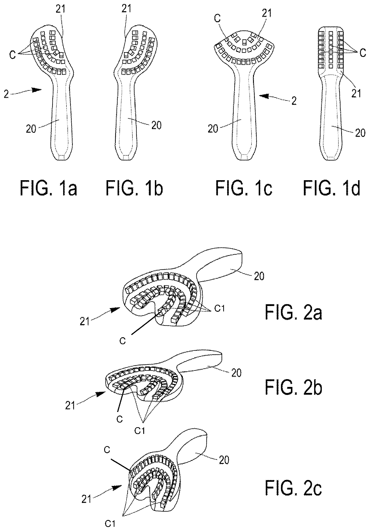
[0061]The present invention consists of an electronic impression device comprising cameras and light projection means, intended to be arranged facing a dental arch of a patient or part of an arch of a patient.

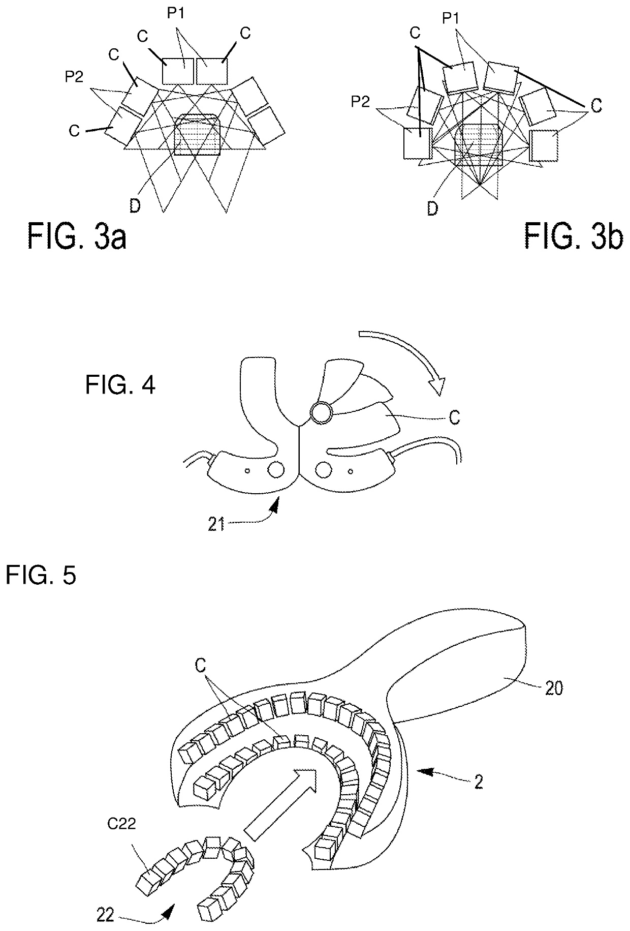
[0062]With reference to FIGS. 1a, 1b, 1c and 1d, different types of the electronic impression device 1 according to the invention can be seen, which comprises an optical measurement sensor system Cl being comprised of a plurality of sensors C, an electronic management system X (See FIG. 20) in communication with the sensors C and being comprised of a central management unit X1 so as to collect, store, and order data obtained by the sensors C (See FIG. 20), and a tray 2 having a dental arch part 21. The sensors C are arranged on the dental arch part 21 of the tray 2, whereby the different types of impression devices 1 shown in these figures each allow the electronic impression of a defined part of a dental arch of the patient to be obtained by the dental arch part 21 of the tray...


PUM


Abstract

An electronic impression tray can be used to obtain three-dimensional and temporal measurements in dentistry. There is a device having optical measurement sensor system, and an electronic system including a central management unit capable of collecting, storing and ordering the data obtained by the sensor systems distributed over all or part of the impression tray. An optical impression of all or part of a dental arch can be obtained with a single or multiple impressions. The tray includes a part having the shape of all or part of a dental arch, and the part can change by virtue of its ability to deform and / or a structure formed by multiple elements that are hinged to one another and / or reversibly assembled and secured to one another, such as to provide the optimal shape.

Description

CROSS-REFERENCE TO RELATED APPLICATIONS[0001]See Application Data Sheet.STATEMENT REGARDING FEDERALLY SPONSORED RESEARCH OR DEVELOPMENT[0002]Not applicable.THE NAMES OF PARTIES TO A JOINT RESEARCH AGREEMENT[0003]Not applicable.INCORPORATION-BY-REFERENCE OF MATERIAL SUBMITTED ON A COMPACT DISC OR AS A TEXT FILE VIA THE OFFICE ELECTRONIC FILING SYSTEM (EFS-WEB)[0004]Not applicable.STATEMENT REGARDING PRIOR DISCLOSURES BY THE INVENTOR OR A JOINT INVENTOR[0005]Not applicable.BACKGROUND OF THE INVENTION1. Field of the Invention[0006]The present invention relates to an electronic impression system for obtaining a three-dimensional view of all or part of a dental arch, for obtaining dental information.[0007]The object of the present invention is more particularly to propose an electronic impression tray usable for obtaining three-dimensional and temporal measurements in dentistry, and which consists of a device comprising optical measurement sensor systems, possibly associated with ultraso...

Claims


Application Information

Patent Timeline
Patent Type & Authority Patents(United States)
IPC IPC(8): A61C9/00A61C17/08A61C17/02
CPCA61C9/0006A61C9/0053A61C17/0208A61C17/08A61C17/0202
Inventor DURETDE VREESE, GUYQUERBES-DURET, VERONIQUE
Owner DURET FRANCOIS
Why Eureka
Try Eureka