
Opto-acoustic signal processing

a technology of opto-acoustic signal processing and signal processing, applied in the direction of optics, optical waveguide light guide, instruments, etc., can solve the problem of fundamentally difficult adaptation of these techniques to integrated systems

Active Publication Date: 2022-07-05
YALE UNIV
View PDF5 Cites 0 Cited by
  • Summary
  • Abstract
  • Description
  • Claims
  • Application Information

AI Technical Summary

Problems solved by technology

While there have been great efforts to miniaturize existing Faraday isolators, it is fundamentally difficult to adapt these techniques to integrated systems since magneto-optic materials are intrinsically lossy and not CMOS-compatible.

Method used


Image

  • Opto-acoustic signal processing
  • Opto-acoustic signal processing
  • Opto-acoustic signal processing

Examples


experimental examples

[0187]The invention is now described with reference to the following Examples. These Examples are provided for the purpose of illustration only and the invention should in no way be construed as being limited to these Examples, but rather should be construed to encompass any and all variations which become evident as a result of the teaching provided herein.

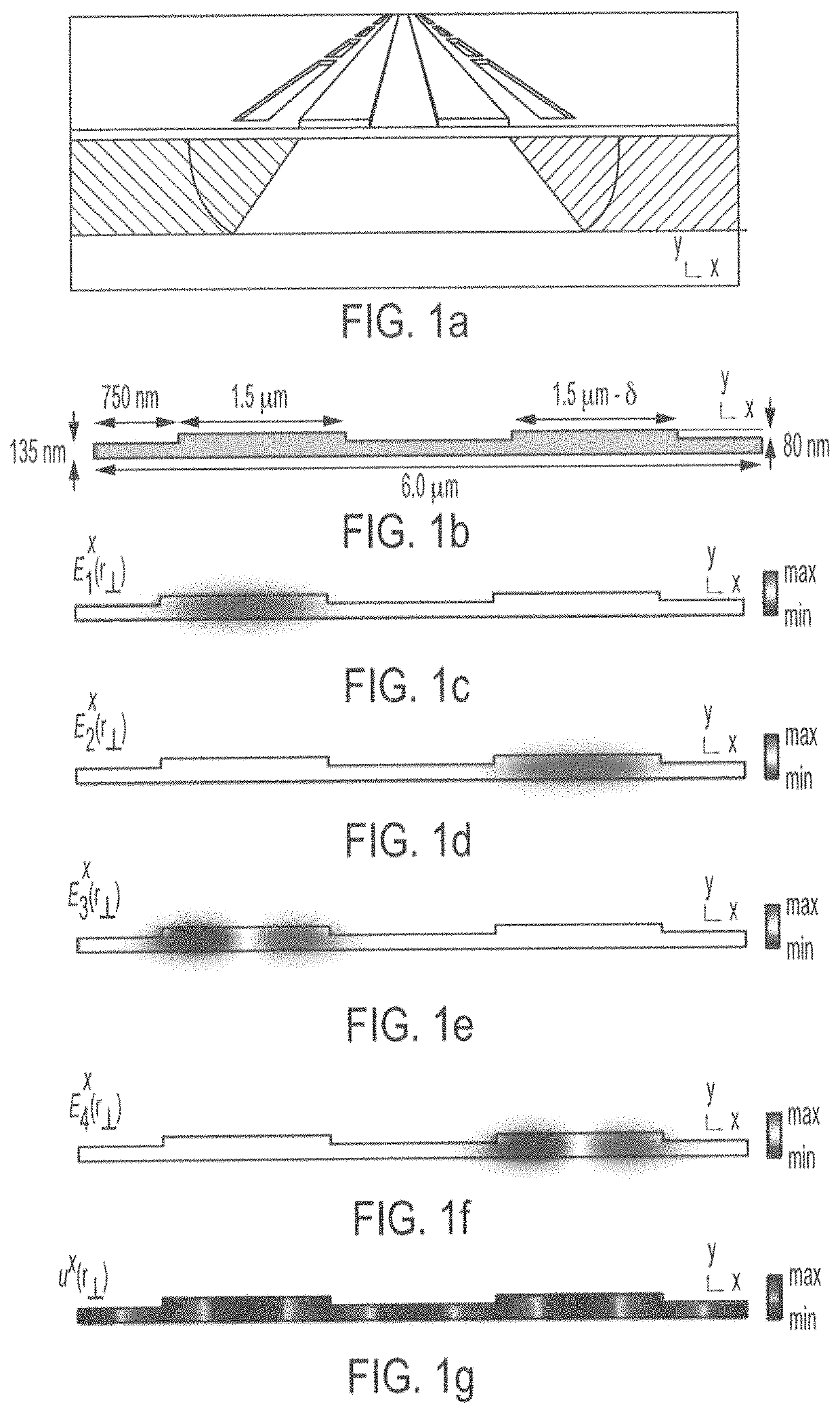
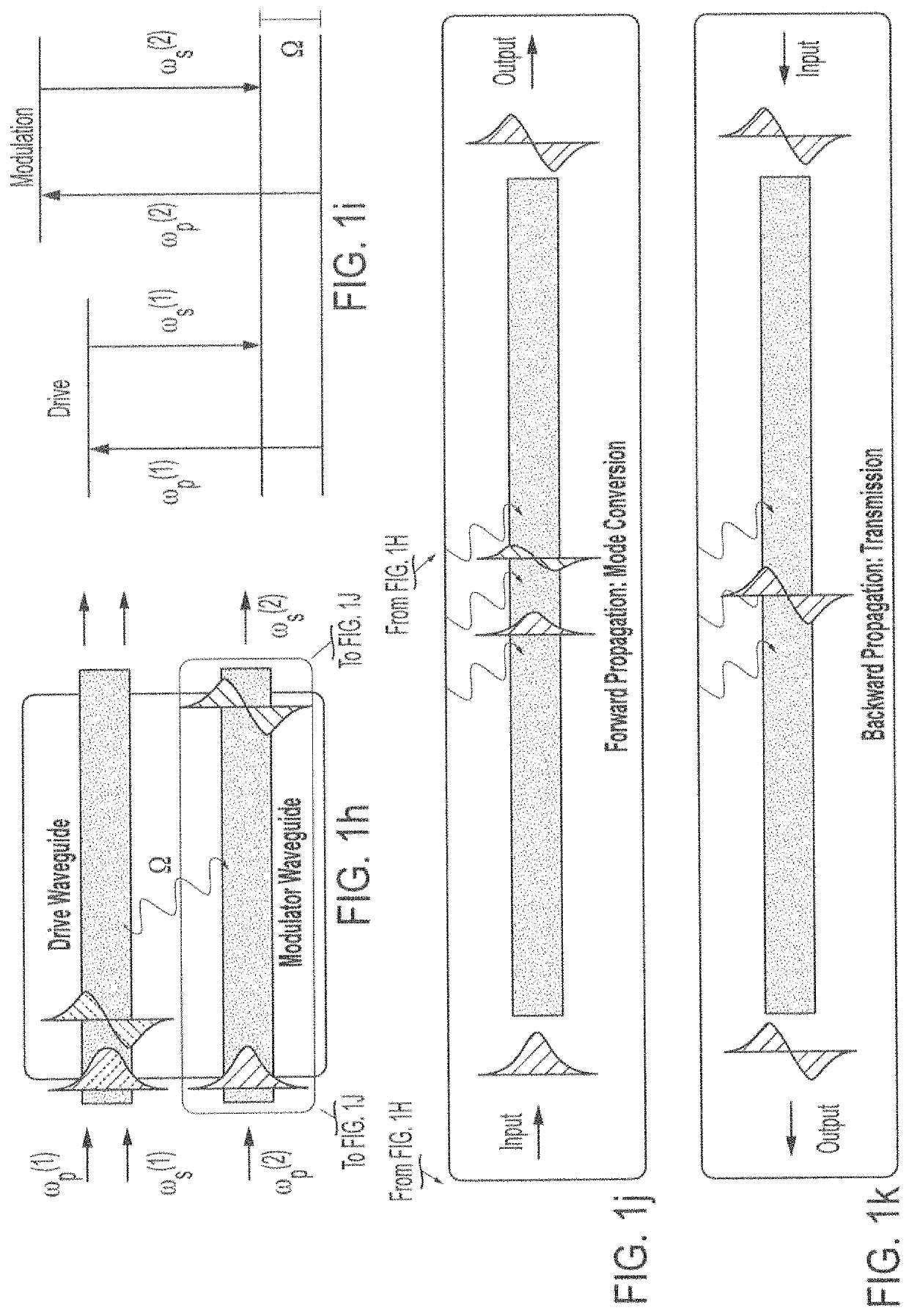
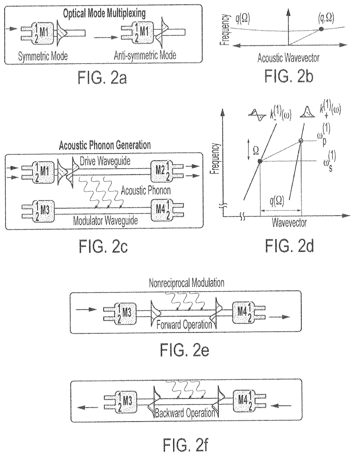
[0188]Without further description, it is believed that one of ordinary skill in the art can, using the preceding description and the following illustrative examples, make and utilize the devices of the present invention and practice the claimed methods. The following working examples therefore and are not to be construed as limiting in any way the remainder of the disclosure. Demonstrated herein is a device that harnesses optically-driven acoustic waves to produce unidirectional optical modulation and mode conversion over nm-bandwidths. This nonreciprocal operation, realized in a low-loss integrated silicon waveguide, utilizes a ...


PUM

PropertyMeasurementUnit
wavelengthaaaaaaaaaa

Abstract

Devices and systems for opto-acoustic signal processing are described herein. In one embodiment, the device may include a structure configured to laterally confine travelling acoustic phonons (hypersound) throughout, a first multimode optical waveguide embedded within the structure, and an acoustic phonon emitter within the structure, where the first multimode optical waveguide is selected to couple to the acoustic phonons (hypersound) confined within the structure. In one embodiment, the system may include a first light source optically coupled to a proximal end of the first multimode optical waveguide, the first light source emitting a probe wave having a frequency ωp(1), and a driver configured to drive the acoustic phonon emitter to emit acoustic phonons (hypersound).

Description

CROSS-REFERENCE TO RELATED APPLICATIONS[0001]This application claims priority under 35 U.S.C. § 119(e) to U.S. Provisional Application No. 62 / 717,299, filed Aug. 10, 2018 which is incorporated herein by reference in its entirety.STATEMENT REGARDING FEDERALLY SPONSORED RESEARCH OR DEVELOPMENT[0002]This invention was made with government support under N00014-16-1-2687 awarded by the Defense Advanced Research Projects Agency and under 1122492 from the National Science Foundation. The government has certain rights in the invention.BACKGROUND OF THE INVENTION[0003]The rapid development of complex integrated photonic circuits has led to a pressing need for robust isolator and circulator technologies to control signal routing and protect active components from back-scatter. While there have been great efforts to miniaturize existing Faraday isolators, it is fundamentally difficult to adapt these techniques to integrated systems since magneto-optic materials are intrinsically lossy and not ...

Claims


Application Information

Patent Timeline
Patent Type & Authority Patents(United States)
IPC IPC(8): G02B6/10G02B6/12G02B6/122G02F1/125
CPCG02B6/1225G02B6/105G02F1/125G02B6/12004G02B6/12007
Inventor KITTLAUS, ERICOTTERSTROM, NILSKHAREL, PRASHANTAGERTLER, SHAIRAKICH, PETER
Owner YALE UNIV
Learn More