Power supply system, server, and power generation facility

a power supply system and server technology, applied in the direction of stationary system fuel cells, fuel cells, electrical equipment, etc., can solve the problems of inconvenience thus deteriorating, and hinder the evaluation of the use results of the power generation facility

Active Publication Date: 2022-07-05
HONDA MOTOR CO LTD
View PDF3 Cites 0 Cited by
  • Summary
  • Abstract
  • Description
  • Claims
  • Application Information

AI Technical Summary

Benefits of technology

[0005]The present invention provides a technique capable of evaluating the use result of a power generation facility more accurately while ensuring the degree of freedom in use of fuel gas by a consumer.

Problems solved by technology

If all fuel gas supplied to a consumer is used by the power generation facility, the consumer cannot use the fuel gas for another purpose, and the convenience thus deteriorates.
This hinders evaluation of the use result of the power generation facility such as charging concerning the power generation facility.

Method used


Image

  • Power supply system, server, and power generation facility
  • Power supply system, server, and power generation facility
  • Power supply system, server, and power generation facility

Examples


Embodiment Construction

[0022]Hereinafter, embodiments will be described in detail with reference to the attached drawings. Note that the following embodiments are not intended to limit the scope of the claimed invention, and limitation is not made to an invention that requires all combinations of features described in the embodiments. Two or more of the multiple features described in the embodiments may be combined as appropriate. Furthermore, the same reference numerals are given to the same or similar configurations, and redundant description thereof is omitted.

Configuration of System

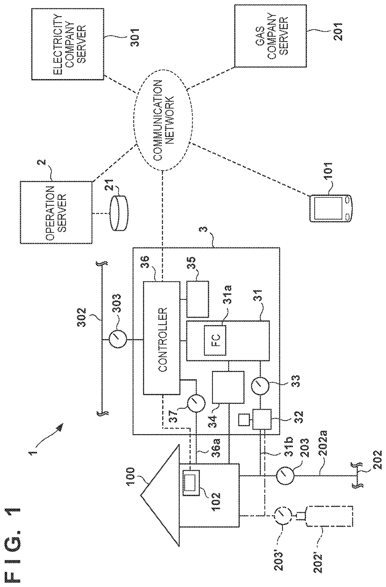
[0023]FIG. 1 is a block diagram of a power supply system 1 according to an embodiment of the present invention. The power supply system 1 includes a power generation facility 3 for supplying power to a consumer 100, and an operation server 2 communicable with the power generation facility 3 via a communication network such as the Internet. In this embodiment, the consumer 100 is used as not only the meaning of a natural per...


PUM

PropertyMeasurementUnit
poweraaaaaaaaaa
degree of freedomaaaaaaaaaa
power consumptionaaaaaaaaaa

Abstract

A power supply system includes a power generation facility configured to supply power to a consumer and a server configured to communicate with the facility. The facility includes a fuel cell configured to generate, using fuel gas supplied via a supply path of the fuel gas to the consumer, power to be supplied to the consumer, and a measurement unit configured to measure a supply amount of the fuel gas used for the power generation. The server includes an acquisition unit configured to acquire information concerning a supply amount of the fuel gas supplied to the consumer, and a specifying unit configured to specify, based on a measurement result of the measurement unit received from the facility and the information, a supply amount of the fuel gas not used for the power generation in the supply amount of the fuel gas supplied to the consumer.

Description

CROSS-REFERENCE TO RELATED APPLICATION(S)[0001]This application claims priority to and the benefit of Japanese Patent Application No. 2020-003858 filed on Jan. 14, 2020, the entire disclosure of which is incorporated herein by reference.BACKGROUND OF THE INVENTIONField of the Invention[0002]The present invention relates to a technique of supplying power to a consumer.Description of the Related Art[0003]There is proposed a system in which a power generation facility including a fuel cell that generates power by fuel gas is installed to supply power to a consumer (Japanese Patent Laid-Open No. 2017-216793). Such system has an advantage that a consumer can make an attempt to reduce an electricity rate, and also has an advantage in using exhaust heat generated by power generation of the fuel cell.[0004]If all fuel gas supplied to a consumer is used by the power generation facility, the consumer cannot use the fuel gas for another purpose, and the convenience thus deteriorates. If the co...

Claims


Application Information

Patent Timeline
Patent Type & Authority Patents(United States)
IPC IPC(8): H01M8/04H01M8/04089H01M8/04858
CPCH01M8/04089H01M8/04932H01M2250/10H01M8/04388
Inventor TSUKAMOTO, KEIJISHINOHARA, MASASHI
Owner HONDA MOTOR CO LTD
Why Eureka
Try Eureka