Eureka AIR delivers breakthrough ideas for toughest innovation challenges, trusted by R&D personnel around the world.

Digital printing system for printing on fabric including foam pretreatment

a digital printing and fabric technology, applied in the direction of dyeing process, printing, liquid/gas/vapor textile treatment, etc., can solve the problems of insufficient printing resolution, and inability to print immediately,

Active Publication Date: 2022-07-19
DOVER EURO SARL
View PDF47 Cites 2 Cited by
  • Summary
  • Abstract
  • Description
  • Claims
  • Application Information

AI Technical Summary

Benefits of technology

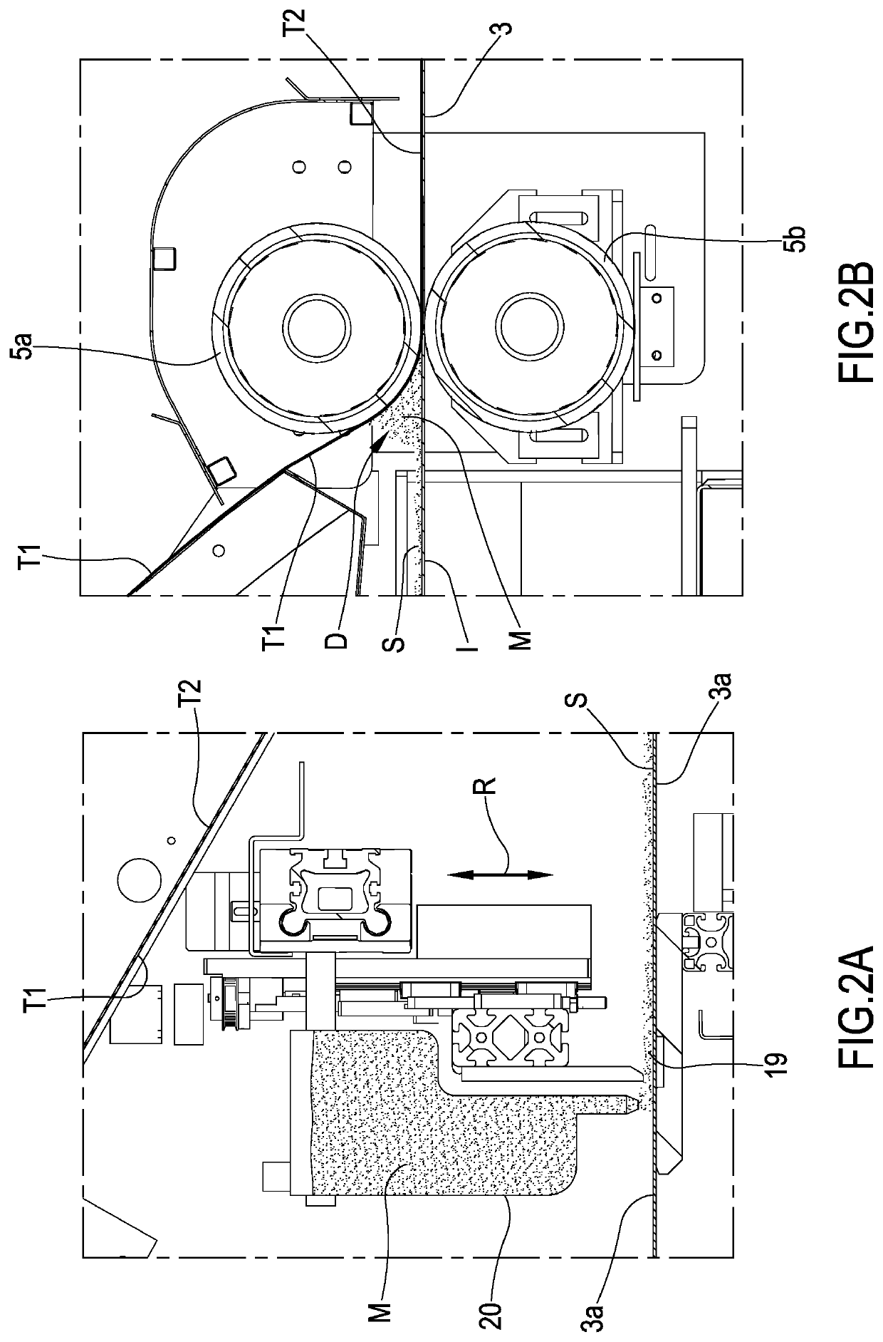
[0011]A first object of the invention consists of providing a plant and an associated printing process enabling an efficient treatment of fibrous materials as discrete sheet or web, for example fabrics, knitted fabrics and / or non-woven fabrics, in order to place the sheet material under optimal conditions for being printed, particularly for being digitally printed. Specifically, it is an object of the invention to provide a plant enabling a controlled and efficient step of treating the sheet material as discrete sheet or continuous web wherein the same is wetted and / or impregnated with pre-treatment substances—for example thickening and / or anti-migration additives—for appropriately preparing the fibrous material for the printing.
[0012]An object of the present invention consists of providing a plant for digitally printing a fibrous material as discrete sheet or continuous web, which enables dedicated printing heads to operate at a reduced distance from the fibrous material in order to ensure high printing resolutions.
[0013]A further object of the invention consists of providing a plant and an associated process of printing fibrous materials as discrete sheet or continuous web, which enable to quickly treat the material itself; particularly it is an object of the present invention to provide a plant enabling to minimize the treatment time of the fibrous material as discrete sheet or continuous web, in order to reduce to the smallest possible amount the time and cost of the printing process.
[0014]Then, it is an object of the invention to provide a printing plant and process which can be implemented with reasonable running costs and offering a high productivity, by minimizing the quantity of the used pre-treatment substances for the sake of the environment.
[0063]commanding the applicator (12) to reduce the deposition flow rate of the treatment composition if the measured value of the movement speed of the conveyor belt (2) is greater than the reference value or range.

Problems solved by technology

Actually, in the digital printing, jet heads having a plurality of nozzles having a small ink passage opening are used: in this situation, it is virtually impossible to directly add the ink because this latter could become, for example, too much viscous, which would prevent the ink from regularly passing through the heads, or could get chemical-physical characteristics which are not easily manageable by the systems controlling the same digital heads.
This pre-treatment substances are typically applied by dipping the fibrous material in suitable tanks: this technique inevitably leaves the material to be printed wet.
Although the above cited apparatuses enable to pre-treat and print sheet fibrous materials, the Applicant has discovered that such apparatuses are however not devoid of some shortcomings and therefore are improvable under different aspects.
De facto, the nowadays known apparatuses comprise an impregnating step which considerably wets the fibrous material so that the material itself, at the end of the impregnating step, cannot be immediately printed or can be printed with a reduced and insufficient printing resolution.

Method used


Image

  • Digital printing system for printing on fabric including foam pretreatment
  • Digital printing system for printing on fabric including foam pretreatment
  • Digital printing system for printing on fabric including foam pretreatment

Examples


Embodiment Construction

[0319]Printing Plant

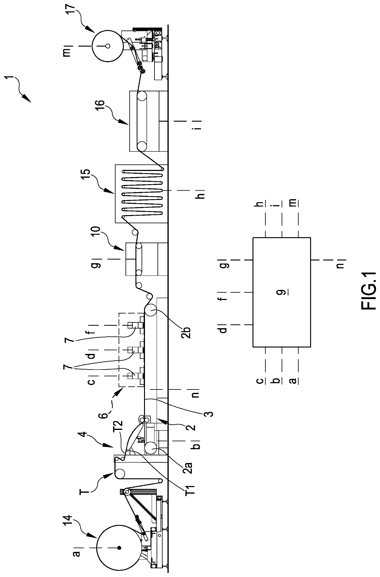
[0320]1 generally indicates a plant for printing, particularly for digitally printing, a sheet fibrous material T, for example as a discrete sheet or as continuous web. The plant 1, object of the invention, is useable for ink-printing at least one side of said sheet fibrous material T which, for example, can be formed by or can comprise a fabric and / or non-woven fabric. Generally, but in a non limiting way, the plant 1 can be applied in the textile or knitted fabric or non-woven fabric industry for printing by ink.

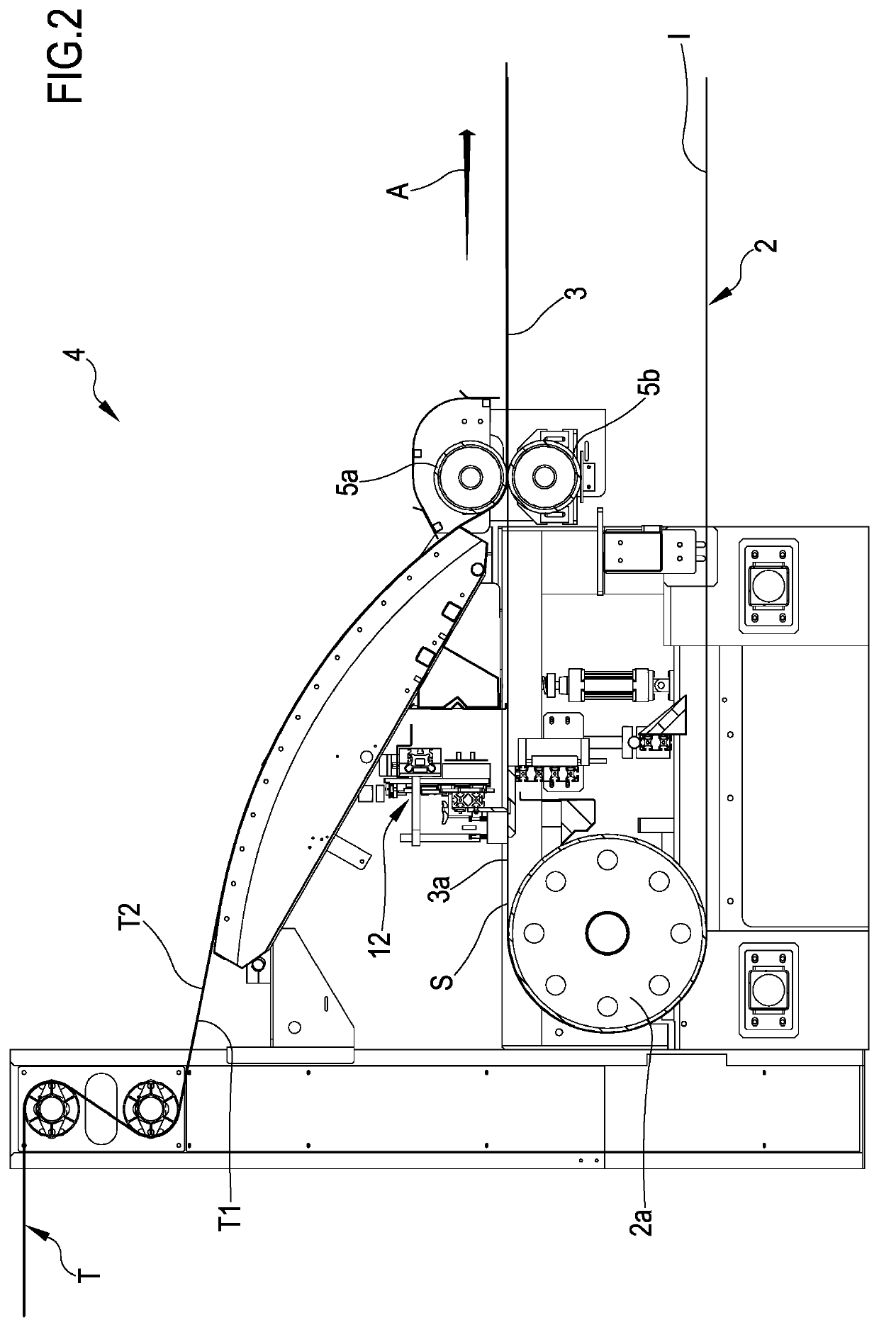
[0321]As it is visible in the attached figures, the plant 1 comprises at least one conveyor belt 2 movable along a closed path, particularly between at least one first and one second end idler members 2a, 2b. The conveyor belt 2 exhibits a structure having two dimensions: length and width (the width is identified by the letter L as illustrated in FIG. 11), substantially prevalent with respect to a third dimension, such as the thickness; the length is de...


PUM

PropertyMeasurementUnit
thicknessaaaaaaaaaa
thicknessaaaaaaaaaa
speedaaaaaaaaaa

Abstract

The present invention refers to a plant (1) for printing a fibrous material (T). The printing plant (1) comprises: a station (14) for supplying a fibrous material configured for supplying the fibrous material along a predetermined operative path, a treating station (10) configured for treating the fibrous material with a treatment composition by applying the composition itself on a first side (T1) of the fibrous material (T); and a printing station (6) configured for ink-printing at least part of a second side (T2) of the fibrous material (T) opposite to the first side (T1). Moreover, the present invention refers to a process of printing a fibrous material.

Description

CROSS-REFERENCE TO RELATED APPLICATIONS[0001]This application is a U.S. National Stage Entry under 35 USC § 371 of International Patent Application No. PCT / IB2017 / 054510, filed on Jul. 25, 2017, which claims the benefit of Italian Patent Application No. 102016000078681, filed on Jul. 27, 2016, both of which are hereby incorporated by reference in their entirety.FIELD OF THE INVENTION[0002]The present invention refers to a printing plant, particularly for digitally printing, a fibrous material having a shape as a discrete sheet or as a web; the invention moreover refers to a process of printing, particularly of digitally printing, said fibrous material as a discrete sheet or web. The plant and the respective process object of the invention can find an application in the field for printing fabrics and / or non-woven fabrics. The invention is generally, but in a non-limiting way, applicable in the textile or knitted fabrics or non-woven fabric industry.STATE OF THE ART[0003]As it is know...

Claims


Application Information

Patent Timeline
Patent Type & Authority Patents(United States)
IPC IPC(8): B41J3/407B41J11/00B41J15/04D06B21/00B41J11/42B41J2/155B41J15/16B41J15/06B41J2/21B41M5/00B41F31/28
CPCB41J3/4078B41J2/155B41J2/2114B41J11/0015B41J11/0095B41J11/42B41J15/048B41J15/06B41J15/165D06B21/00B41F31/28B41J11/00216B41M5/0011B41M5/0047B41M5/0064D06B1/148D06B11/0089D06P5/30D06B11/0059D06B1/16D06B19/0094
Inventor MILINI, LUIGI
Owner DOVER EURO SARL
Why Eureka
Eureka Blog
Learn More