Supercharge Your Innovation With Domain-Expert AI Agents!

Composite vehicle driveshaft with welded joint system

a technology of welded joint and drive shaft, which is applied in the direction of mechanical equipment, couplings, other domestic objects, etc., can solve the problems of torsional loading, stricter diameter and other size constraints, and the inability to widely implement a drive shaft for vehicles

Active Publication Date: 2022-07-19
COMPOSITE DRIVELINES LLC
View PDF70 Cites 0 Cited by
  • Summary
  • Abstract
  • Description
  • Claims
  • Application Information

AI Technical Summary

Benefits of technology

The invention provides a way to make composite vehicle driveshafts by using modular joint-to-tube adapter-type components that can be easily assembled and bonded onto composite tubes. This allows for the use of composite tubes as a torque-transferring component of a driveshaft while still providing fully metallic joints at the input and output ends of the driveshaft. This capability makes it easy to fabricate and repair these driveshafts, and allows for custom and aftermarket implementations.

Problems solved by technology

However, composite driveshafts have not been widely implemented for vehicle use.
Designing composite driveshafts with composite tubes that connect to metallic components such as conventional vehicle driveline components presents numerous challenges.
Vehicle driveshafts operate in heat envelopes that expose them to high operating temperatures and large temperature variations, operate at high rotational speeds and with large rotational speed variations, and experience substantial torsional loading conditions such as shock-loads and / or other extreme torque spikes, and are subject to stricter diameter and other size constraints.
It is difficult to design and assemble joints, fittings, or adapters to transition from the composite tubes to conventional driveline components that can maintain connection integrity with the composite tubes while handling these operating conditions and that are also sufficiently manufacturable and economical.
Besides these numerous technical challenges, some driveshaft-industry companies, including various custom and other aftermarket driveshaft manufacturers and providers, as well as local driveshaft building / repair shops, are unable to produce composite driveshafts because their facilities are set up to only work with metal driveshaft components.

Method used


Image

  • Composite vehicle driveshaft with welded joint system
  • Composite vehicle driveshaft with welded joint system
  • Composite vehicle driveshaft with welded joint system

Examples


Embodiment Construction

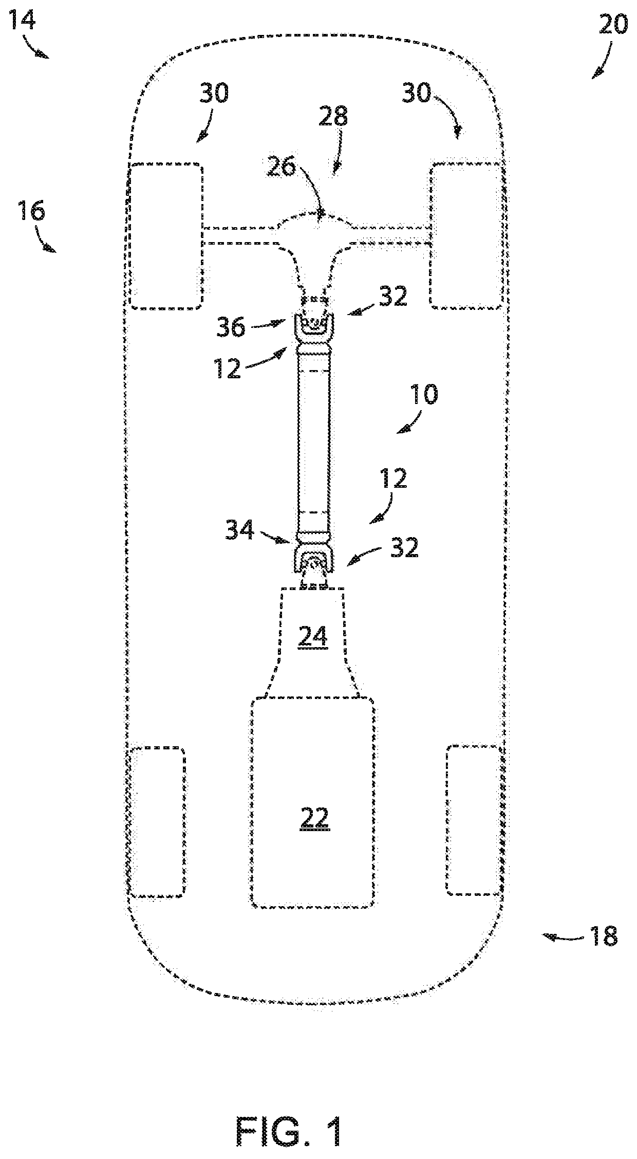
[0019]Referring now to the drawings and initially to FIG. 1, a composite vehicle driveshaft 10 with at least one welded joint system, shown here as a pair of welded joint systems 12 implemented in a vehicle 14, is represented here as an automobile 16. Automobile 16 has front and rear ends 18, 20 and a powertrain that includes a prime mover such as engine 22. Transmission 24 receives power from the engine 22 and delivers it downstream through the composite vehicle driveshaft 10 to a differential 26 that delivers the power through a drive axle 28 to a pair of drive wheels 30. Welded joint systems 12 are shown respectively connecting the driveshaft front end 34 to the transmission 24 and the driveshaft rear end 36 to the differential 26. It is understood that instead of the transmission 24 and differential 28, the composite vehicle driveshaft 10 may instead transmit power from the engine 22 to a transaxle that combines a transmission and drive axle.

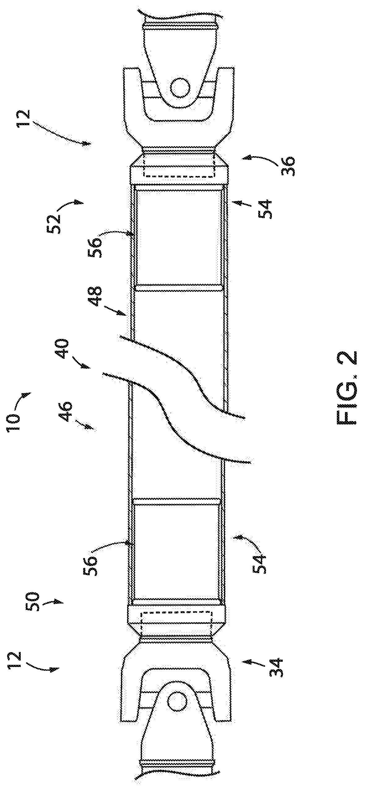
[0020]Referring now to FIG. 2, compos...


PUM

PropertyMeasurementUnit
angleaaaaaaaaaa
angleaaaaaaaaaa
angleaaaaaaaaaa

Abstract

A composite vehicle driveshaft is provided with a composite tube and a welded joint system(s) at one or both ends of the composite tube for connecting the composite vehicle driveshaft to driveline components. Each welded joint system may include a sleeve that is bonded to an end of the composite tube and a joint assembly that is welded to the sleeve.

Description

CROSS-REFERENCE TO RELATED APPLICATIONS[0001]This application claims the benefit of U.S. Provisional Patent Application No. 62 / 652,030, filed Apr. 3, 2018, hereby incorporated by reference in its entirety.FIELD OF THE INVENTION[0002]The invention relates generally to vehicle propel shafts or driveshafts that are made from composite materials. The invention additionally relates to a composite vehicle driveshaft with a welded joint system that allows application versatility, which may facilitate custom and other aftermarket implementations.BACKGROUND OF THE INVENTION[0003]Composite driveshafts are available, which have resulted from efforts to provide weight reduction for rotating assemblies. However, composite driveshafts have not been widely implemented for vehicle use. Designing composite driveshafts with composite tubes that connect to metallic components such as conventional vehicle driveline components presents numerous challenges.[0004]The composite tubes of composite vehicle d...

Claims


Application Information

Patent Timeline
Patent Type & Authority Patents(United States)
IPC IPC(8): F16C3/02F16D3/38B29C65/54B29C65/00B23K101/04
CPCF16C3/026B29C65/542B29C66/742F16D3/387B23K2101/04F16C2208/02F16C2226/36F16C2226/40F16C2326/06Y10T403/473F16C3/023F16C2361/31B29C66/721B29C65/54B29C66/1222B29C66/1224B29C66/522B29C66/542B29C66/5432B29L2031/75B29L2031/3055
Inventor DORMAN, JAMES LEEBERNDT, KAI-PETERPIPER, GREGG
Owner COMPOSITE DRIVELINES LLC
Features
  • R&D
  • Intellectual Property
  • Life Sciences
  • Materials
  • Tech Scout
  • Unparalleled Data Quality
  • Higher Quality Content
  • 60% Fewer Hallucinations
Learn More