
Valance system for window coverings

a window covering and valance technology, applied in the field of window coverings, can solve the problems of no standard or convenient method of installing a valance, the appearance of the track system and the bracketry used to hang and operate the shade material is unappealing, and the process is extremely time-consuming

Active Publication Date: 2022-07-26
CURRENT PROD CORP
View PDF48 Cites 0 Cited by
  • Summary
  • Abstract
  • Description
  • Claims
  • Application Information

AI Technical Summary

Benefits of technology

The patent describes a system for installing a valance on a window covering. The valance can be folded and placed in a shipping box with other parts, making it easy to install. The valance has a clip feature that can be removed in sections to bend it. It is covered with a covering material and an end cap can be connected to the valance. The clip feature fits snugly into a bracket, making it easy to install without tools. Overall, the system is affordable, standardized, and easy to install.

Problems solved by technology

One problem with drapery systems is that the track system and bracketry that is used to hang and operate the shade material tends to have an unappealing appearance.
However, due to there being countless forms and designs of drapery systems, there is no standard or convenient method of installing a valance.
While effective, this process is extremely time consuming, labor intensive and many times it leads to a finished product that is less than optimal.
In addition, custom fabricating a valance often produces a finished product that uses more materials than is necessary, is heavier than is necessary, is more complicated and difficult to install than is necessary, and can provide a substantial safety hazard if installed improperly.
In addition, removing and replacing these custom fabricated valances tends to suffer from the same disadvantages.
Another problem related to current valance systems is that they often are misaligned and they are substantially impacted by the way in which they are installed.
In addition, current valance systems are not able to be adjusted to correct any misalignment causing the resulting installation to be less than desirable.

Method used


Image

  • Valance system for window coverings
  • Valance system for window coverings
  • Valance system for window coverings

Examples


Embodiment Construction

[0148]In the following detailed description, reference is made to the accompanying drawings which form a part hereof, and in which is shown by way of illustration specific embodiments in which the invention may be practiced. These embodiments are described in sufficient detail to enable those skilled in the art to practice the invention, and it is to be understood that other embodiments may be utilized and that mechanical, procedural, and other changes may be made without departing from the spirit and scope of the invention. The following detailed description is, therefore, not to be taken in a limiting sense, and the scope of the invention is defined only by the appended claims, along with the full scope of equivalents to which such claims are entitled.

[0149]As used herein, the terminology such as vertical, horizontal, top, bottom, front, back, end, sides, and the like, are referenced according to the views presented and / or the orientation of the parts / components with respect to on...


PUM


Abstract

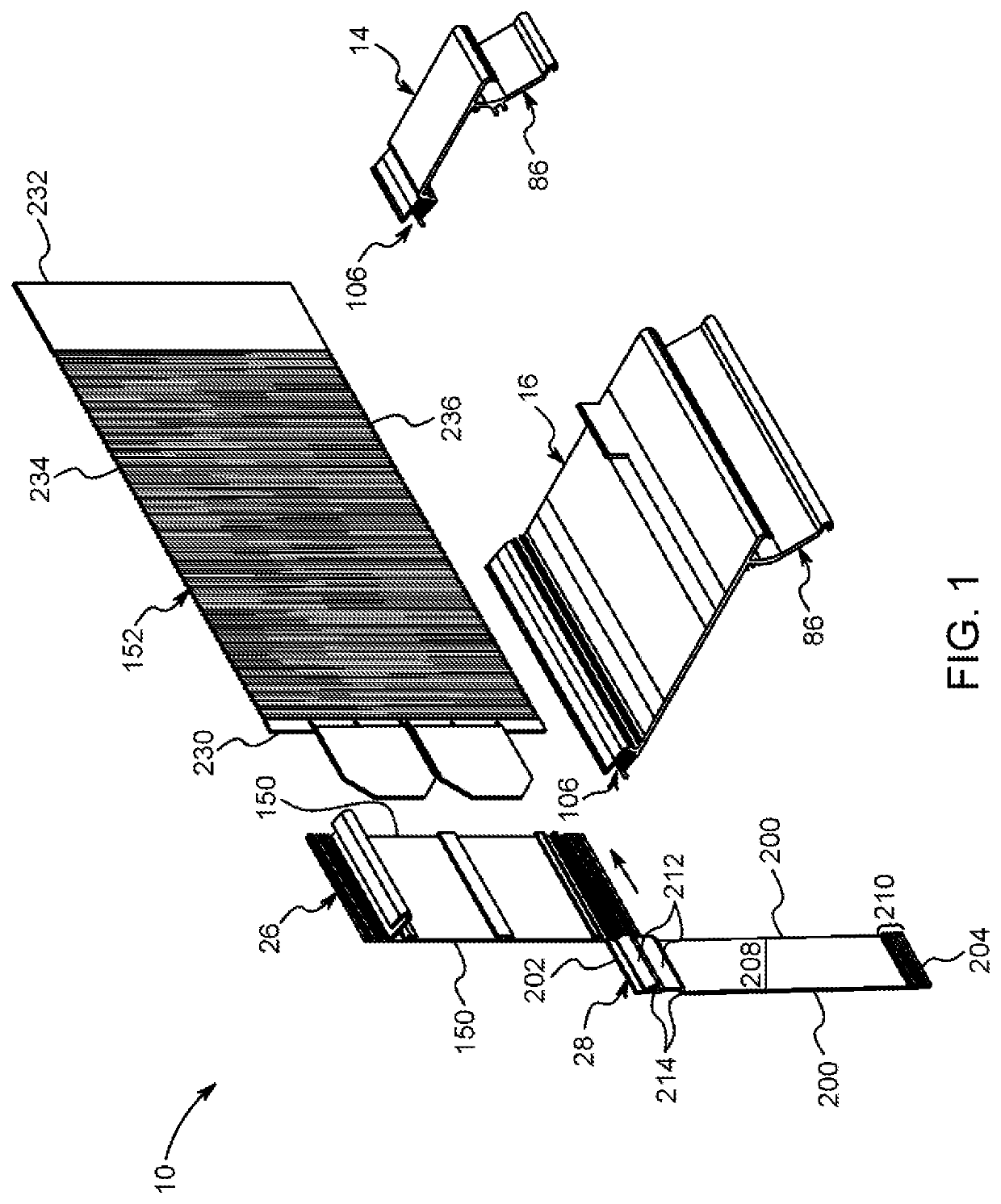
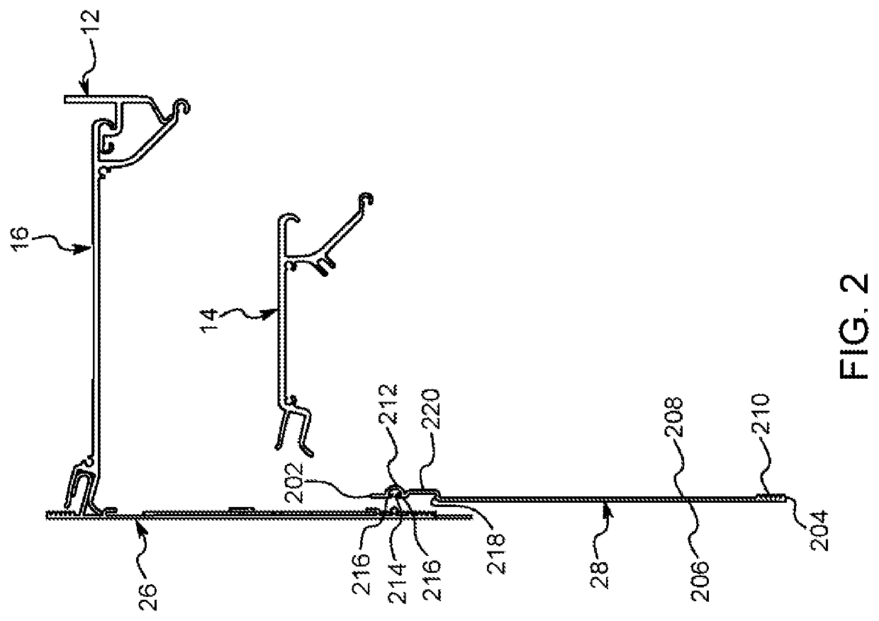
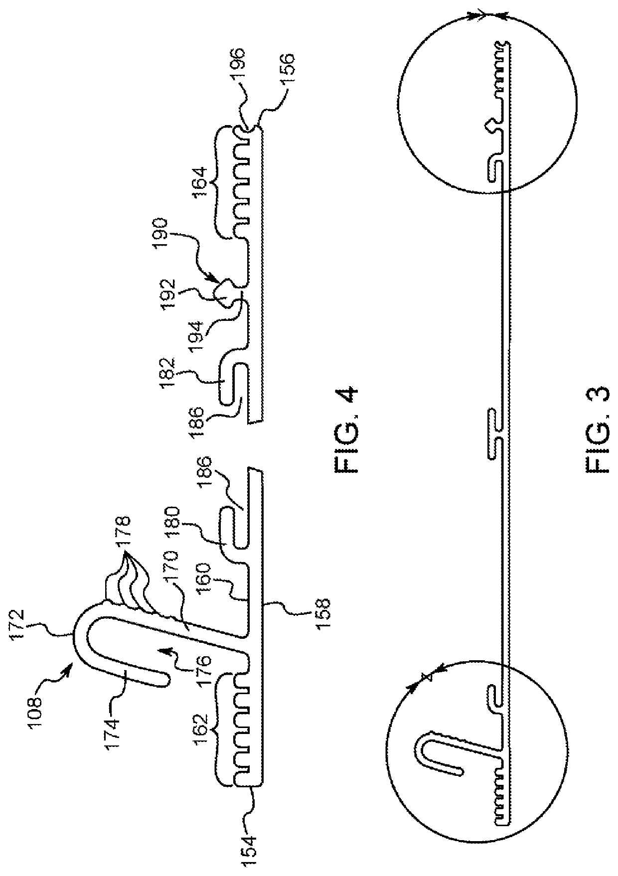
A valance system for a window covering that can be folded and placed within the same shipping box as a wall bracket, top bracket and track sections. The valance extends a length between opposing ends and includes a clip feature that extends out from its rearward side. The clip feature is generally C-shaped or U-shaped when viewed from the side and includes a plurality of friction members in its exterior surface. The valance is covered with a covering material. An end cap having a hinge area that facilitates bending of the end cap is connected to the ends of the valance by connection of a tongue of the end cap to a slot of the valance. The clip feature is sized and shaped to frictionally fit within and be installed within a socket of a top bracket without any tools.

Description

CROSS-REFERENCE TO RELATED APPLICATION[0001]This application is a continuation-in-part to and claims priority to United States Patent and Trademark Office Utility patent application Ser. No. 15 / 413,973 filed on Jan. 24, 2017 and published as U.S. Pat. Pub. No. 2017 / 0208980 which itself claims priority from United States Patent and Trademark Office Provisional Application No. 62 / 286,689 filed Jan. 25, 2016.FIELD OF THE INVENTION[0002]This invention relates to window coverings. More specifically, this invention relates to a valance system for window coverings.BACKGROUND OF THE INVENTION[0003]Window coverings are frequently used to provide privacy and to limit the amount of light that is permitted to pass through a window and into a room. There are numerous types of window coverings known in the art. One form of window coverings, which are of particular interest to this application, are known as drapes (or drapery), curtains, vertical blinds, drapery tracks, or the like which hang from...

Claims


Application Information

Patent Timeline
Patent Type & Authority Patents(United States)
IPC IPC(8): A47H2/00A47H3/02
CPCA47H2/00A47H3/02
Inventor MULLET, WILLIS JAYMATTHEWS, DANIEL T.HAND, RICHARD SCOTTASBURY, HARRY EDWARD
Owner CURRENT PROD CORP
Learn More