Inflation valve with bulb having a bisymmetric cavity for passage of a tubular core

a tubular core and inflation valve technology, applied in the field of inflation valves, can solve the problems of limiting the performance level at high speed, poor performance of elastic deformation type inflation valves compared with other types of valves, and difficult to insert the complete valve into the rim orifi

Active Publication Date: 2022-08-09
CONTINENTAL AUTOMOTIVE GMBH
View PDF15 Cites 0 Cited by
  • Summary
  • Abstract
  • Description
  • Claims
  • Application Information

AI Technical Summary

Benefits of technology

[0031]The first two cavity portions, which are larger, facilitate the mounting of the inflation valve in the rim orifice, and the second, smaller, cavity portions make it possible to increase the mechanical strength, and therefore the durability, of the inflation valve in the rim orifice.
[0032]As well as improving the dynamic performance and retaining the ease of mounting, an aspect of the invention makes it unnecessary to provide any keying with respect to the casing. The inflation valve may equally well be mounted at 0° or 180°, that is to say with a second direction extending radially to the rim in both cases. This advantage is important for after-sales service, for which only one spare inflation valve is sold.
[0033]The bisymmetry of the inflation valve according to an aspect of the present invention enables it to be compatible for forming a wheel unit with sensors that are already in production. The bisymmetry is with respect to an axis passing through first direction and an axis passing through second direction, with different deviations in the first and second directions.
[0034]The joggling of the valve and sensor around the rim orifice is reduced, again due to increased rubber thickness in the second direction which is radial to the rim when the inflation valve is mounted. This enables the joggling and fatigue of the elastic material of the bulb, notably rubber, to be reduced.
[0038]Advantageously, the cavity extends axially in the bulb between a first plane perpendicular to the tubular core passing through the external edge of the groove and a second plane perpendicular to the tubular core which is nearer to the internal longitudinal end of the bulb than is the internal edge of the groove. The cavity may extend at least over a length running from the external edge of the rim hole to the internal edge of the rim hole. However, it is advantageous to make it even larger, in order to strengthen its effect.

Problems solved by technology

In both cases, during travel, the rubber bulb of the valve will stretch more and more until a leak or a tear in the rubber is created, thus limiting performance levels at high speed.
Inflation valves of the elastic deformation type have poor performance compared with other types of valve, called screw-in valves, owing to the low strength of the elastic materials of the bulb when subjected to high acceleration.
If the valve cavity is reduced to increase the amount of rubber and therefore the dynamic performance, it is difficult to insert the complete valve into the rim orifice for receiving the valve, owing to the small cavity volume available to allow for the deformation of the bulb made of elastic material, notably rubber.
If the valve cavity is enlarged to facilitate the insertion of the valve into the rim orifice, the retention of the bulb in the rim orifice is decreased and the inflation valve becomes impaired.
Furthermore, a relatively large cavity intended to be directed toward the interior increases the possible clearance of the tubular core and therefore leads to additional fatigue of the elastic material of the bulb.

Method used


Image

  • Inflation valve with bulb having a bisymmetric cavity for passage of a tubular core
  • Inflation valve with bulb having a bisymmetric cavity for passage of a tubular core

Examples


Embodiment Construction

[0055]In the following text, internal and external are considered with reference to the motor vehicle wheel rim, any element inside the rim and therefore inside the tire being qualified as internal and any element outside the rim and therefore outside the tire being qualified as an external element.

[0056]The term “valve” may equally well denote an inflation valve used solely for inflation and for sealing the tire borne by the rim, but may also denote a valve performing other functions by being a wheel unit, as mentioned above. Thus, the valve can incorporate an electronic unit for measuring at least one operating parameter of a tire, such as pressure, temperature, speed of rotation of the tire or other parameters.

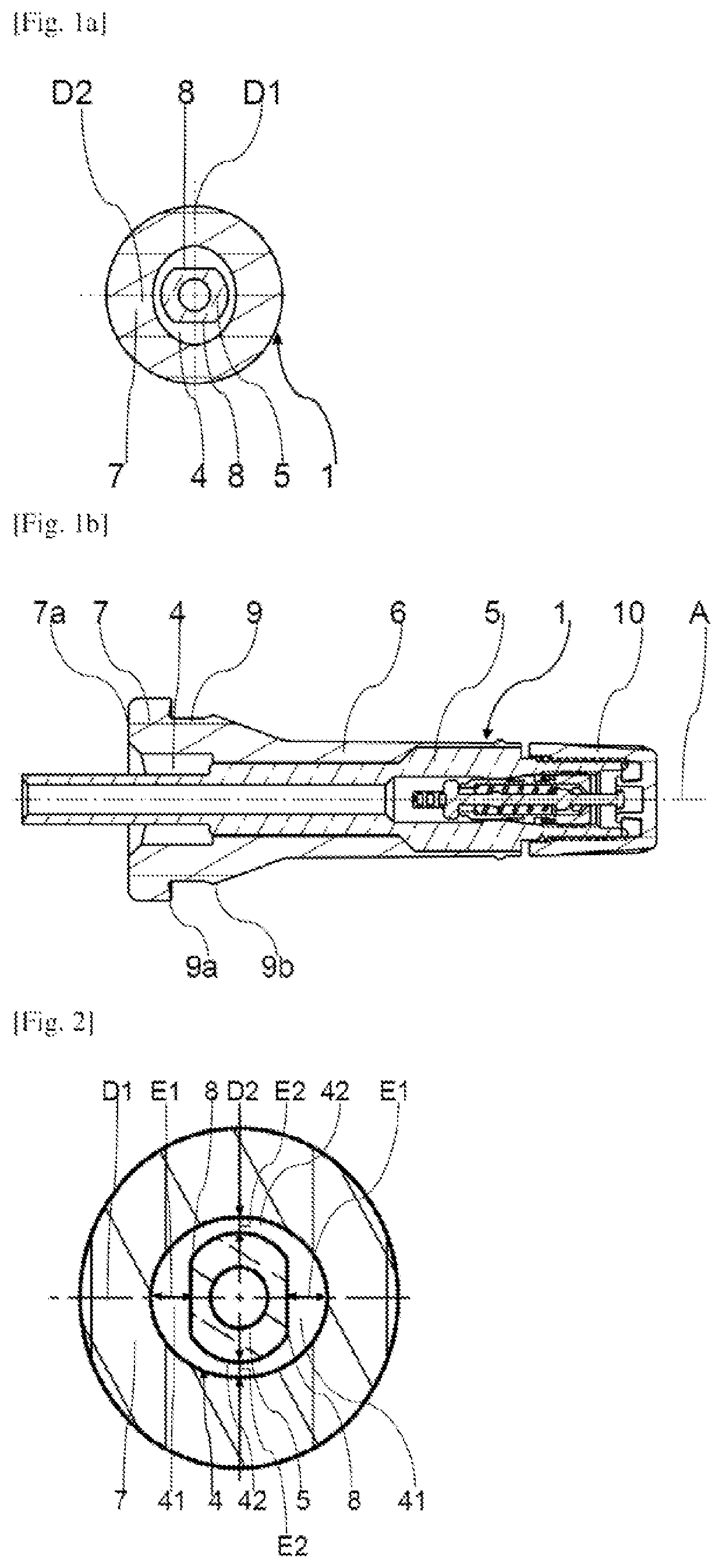
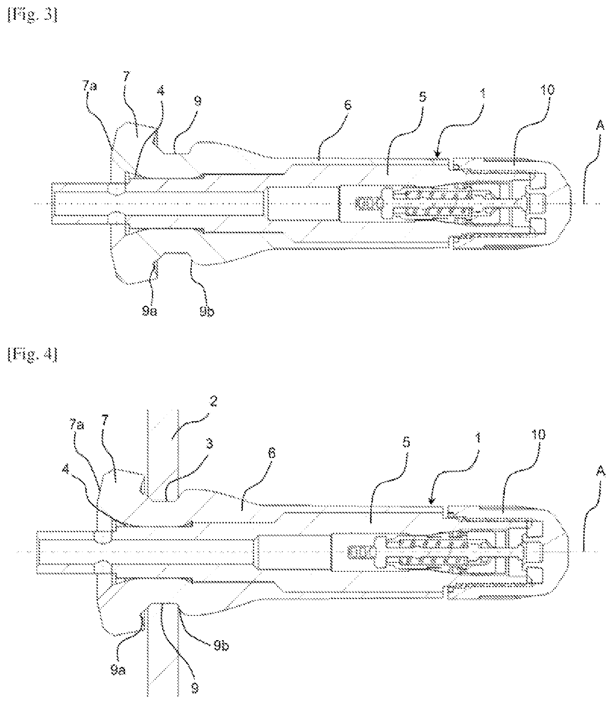
[0057]With reference to all the figures, and mainly to FIGS. 1B, 3 and 4, an aspect of the present invention relates to an inflation valve 1 to be positioned in an orifice 3 of a wheel rim 2 of a motor vehicle, an orifice 3 and a wheel rim 2 of a motor vehicle being illustr...


PUM


Abstract

An inflation valve having a tubular core surrounded with an elastically deformable sleeve with a bulb widening toward the internal longitudinal end of the valve and bearing a sealing groove on its outer contour, the groove being adapted for receiving an edge of the orifice of the rim in its interior. There is a cavity between the bulb and the tubular core, having an oval-shaped outer periphery and a first spacing taken in a first direction radial to the tubular core that is greater than a second spacing taken in a second direction perpendicular to the first direction, a cross section of the inflation valve taken at the position of the cavity exhibiting symmetry with respect to the first and second directions.

Description

CROSS REFERENCE TO RELATED APPLICATIONS[0001]This application is the U.S. National Phase Application of PCT International Application No. PCT / EP2020 / 057943, filed Mar. 23, 2020, which claims priority to French Patent Application No. 1902996, filed Mar. 22, 2019, the contents of such applications being incorporated by reference herein.FIELD OF THE INVENTION[0002]The present invention relates to an inflation valve to be positioned in a wheel rim orifice of a motor vehicle, the valve being of the elastic deformation type, this inflation valve having a cavity that is left empty between a bulb forming part of a sleeve and a tubular core.[0003]The present invention also relates to an assembly of a wheel rim of a motor vehicle and of such an inflation valve.BACKGROUND OF THE INVENTION[0004]Such a valve has a tubular core adapted to form an internal air passage from an external longitudinal end of the valve to an internal longitudinal end, “external” and “internal” being taken to refer to t...

Claims


Application Information

Patent Timeline
Patent Type & Authority Patents(United States)
IPC IPC(8): B60C29/02B60C29/00B60C23/04
CPCB60C29/02B60C23/0494B60C29/005
Inventor DE FENOYL, BAPTISTELEGER, GUILLAUME
Owner CONTINENTAL AUTOMOTIVE GMBH
Why Eureka
Try Eureka