Method for creating multiple electrical current pathways on a work piece

a work piece and multiple technology, applied in the direction of electrophoretic coating, liquid/solution decomposition chemical coating, coating, etc., can solve the problems of adding significant cost to the final product, affecting reducing the aesthetics of work pieces, so as to eliminate the need for costly secondary operations and reduce the cost of post-treatment. cost and other issues

Active Publication Date: 2022-08-09
LACKS ENTERPRISES
View PDF12 Cites 0 Cited by
  • Summary
  • Abstract
  • Description
  • Claims
  • Application Information

AI Technical Summary

Benefits of technology

[0011]It is therefore an aspect of the present disclosure to provide a method for plating a work piece with multiple surface finishes. The method eliminates the need for costly secondary operations to finish the work piece since creating the barrier in electrical conductivity and respectively electroplating the first and second segments of the work piece may be done in an inexpensive and simple process.

Problems solved by technology

This practice, while effective, results in multiple operations and multiple sets of tooling which adds significant cost to the final product.
However, when such work pieces, which include one section employing these surface effects and another part without these effects, are both subjected to electroplating, the leveling characteristic of the electroplated layer on these two sections does not create the visual effect of two distinct metal surface finishes as desired.
Also, the pre and post surface treatments are costly and require an additional operation.
Vacuum metallization and chemical vapor deposition techniques are able to achieve a final product that has segments with different finishes, but are very costly and limited from a performance standpoint in many environments because of the thin layer of metal that results from these techniques.
This additional step increases labor costs and creates an “orange peel” look due to the fact that the organic coating is not completely smooth.
Although this method creates the desired effect, it disadvantageously requires an additional painting operation which adds cost to the final product.

Method used


Image

  • Method for creating multiple electrical current pathways on a work piece
  • Method for creating multiple electrical current pathways on a work piece
  • Method for creating multiple electrical current pathways on a work piece

Examples


Embodiment Construction

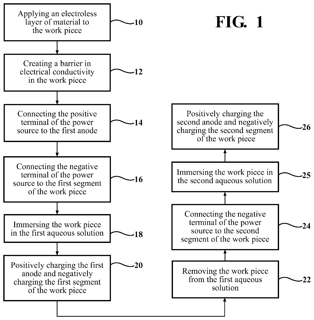
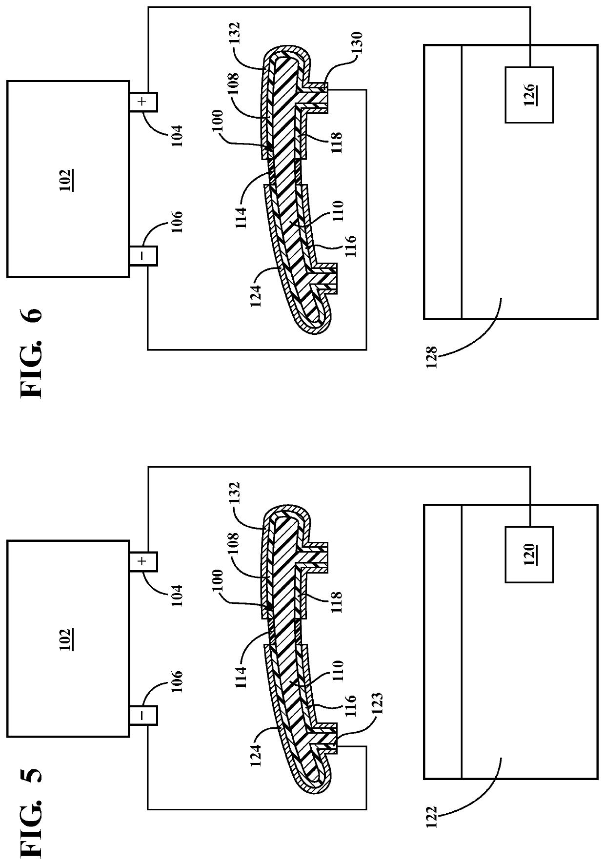
[0020]Referring to the Figures, wherein like numerals indicate corresponding parts throughout the several views, a method is generally shown for plating a work piece 100 using a power source 102 (e.g., a battery) having a positive terminal 104 and a negative terminal 106. It will be appreciated that a variety of suitable power sources may be employed.

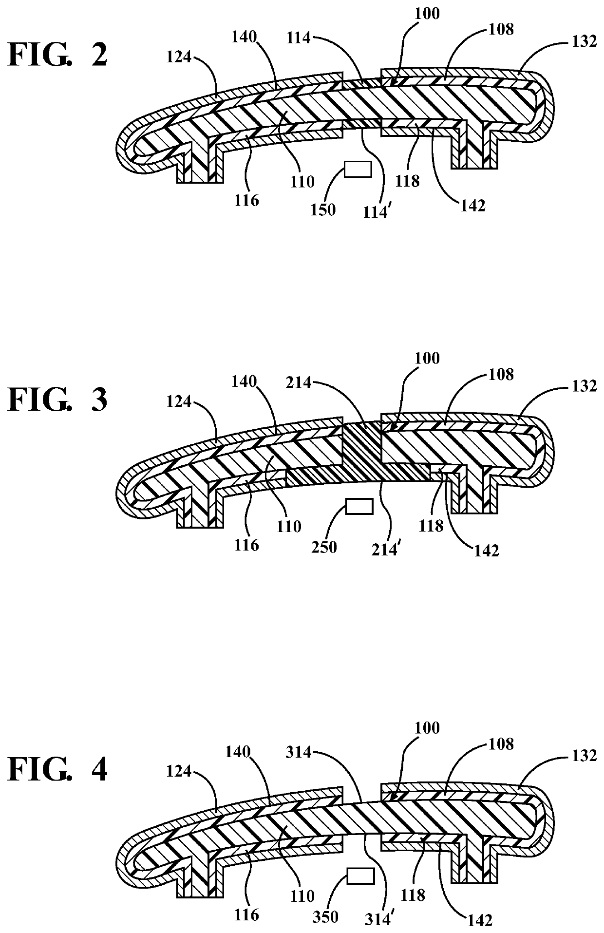
[0021]According to an aspect, as exemplarily shown in FIGS. 1-4, the method includes creating a barrier 114 to electrical conductivity in a base substrate layer 110 of the work piece 100. Thereafter, an electroless layer of material 108 can be applied to the base substrate layer 110 of the work piece 100 using an electroless plating process, as generally indicated by reference number 10. As known in the art, the electroless plating process generally includes an autocatalytic chemical reaction which causes a metal to be deposited on the base substrate layer 110 of the work piece 100 such that the substrate layer 110 will be conductive. A...


PUM

PropertyMeasurementUnit
electrical conductivityaaaaaaaaaa
conductiveaaaaaaaaaa
currentaaaaaaaaaa

Abstract

A method for plating a work piece. An electroless layer of material is applied to the work piece using an electroless plating process. The method includes creating a barrier in electrical conductivity in the work piece to divide the work piece into a first segment and a second segment which are substantially electrically insulated from one another, prior to electroplating the work piece. A plurality of methods are disclosed for dividing the work piece into the first and second segments.

Description

TECHNICAL FIELD[0001]The present disclosure relates generally to improved aesthetics for work pieces, including by a method of electroplating. More specifically, the present disclosure relates to a method for creating multiple electrical current pathways on a work piece to allow for the presence of multiple separate finishes on a single plastic work piece.BACKGROUND OF THE DISCLOSURE[0002]Plated decorative chrome finishes have long been available for various products in the automotive, appliance, consumer electronics, and household application industries. Variations in the deposition methods, processing conditions, and solution makeup of the various types of metals have subsequently resulted in aesthetic variations in the final product. These variations in processing, chemical, and deposition techniques are able to generate different color metal finishes, lower gloss levels, and less distinction of image (DOI) in the metal finish of work pieces all with an eye to improving aesthetic...

Claims


Application Information

Patent Timeline
Patent Type & Authority Patents(United States)
IPC IPC(8): C25D5/02C25D5/56C25D13/02C25D13/20C25D13/22C23C18/16C25D13/12
CPCC25D5/022C23C18/1605C23C18/1653C25D5/02C25D5/56C25D13/02C25D13/12C25D13/20C25D13/22
Inventor LAVALLEE, MICHAEL
Owner LACKS ENTERPRISES
Why Eureka
Try Eureka