
Extendible whipstock, and method for increasing the bend radius of a hydraulic jetting hose downhole

a technology of hydraulic jetting hose and whipstock, which is applied in the direction of drilling machines and methods, directional drilling, borehole/well accessories, etc., can solve the problem that the whipstock body can only provide a limited arcuate path

Active Publication Date: 2022-08-09
COILED TUBING SPECIALTIES
View PDF96 Cites 1 Cited by
  • Summary
  • Abstract
  • Description
  • Claims
  • Application Information

AI Technical Summary

Benefits of technology

The patent describes an apparatus for hydraulic jetting in oil and gas wells that includes a telescoping extension or "sleeve" that can be extended and retracted to guide the jetting assembly in a desired direction. The telescoping sleeve allows the jetting assembly to extend and bend the arcuate path defined by the whipstock in a longer distance than the whipstock itself, which increases the bending stress on the jetting hose and reduces the efficiency of the hydraulic jetting operation. The telescoping sleeve also allows for the use of larger jetting hose with larger inner and outer diameters, reducing frictional forces and increasing the fluid volume throughput. Overall, the telescoping sleeve improves the efficiency and economics of the hydraulic jetting operation.

Problems solved by technology

In contrast, without a telescoping sleeve, the whipstock body can only provide a limited arcuate path for the jetting assembly, because it is confined by the diameter of the wellbore.

Method used


Image

  • Extendible whipstock, and method for increasing the bend radius of a hydraulic jetting hose downhole
  • Extendible whipstock, and method for increasing the bend radius of a hydraulic jetting hose downhole
  • Extendible whipstock, and method for increasing the bend radius of a hydraulic jetting hose downhole

Examples


Embodiment Construction

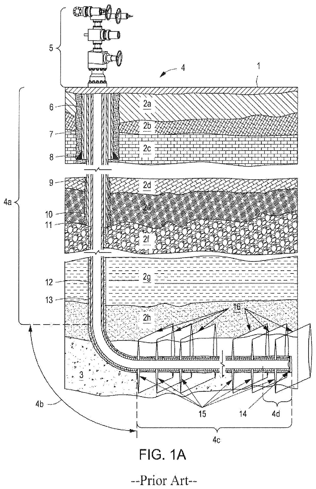
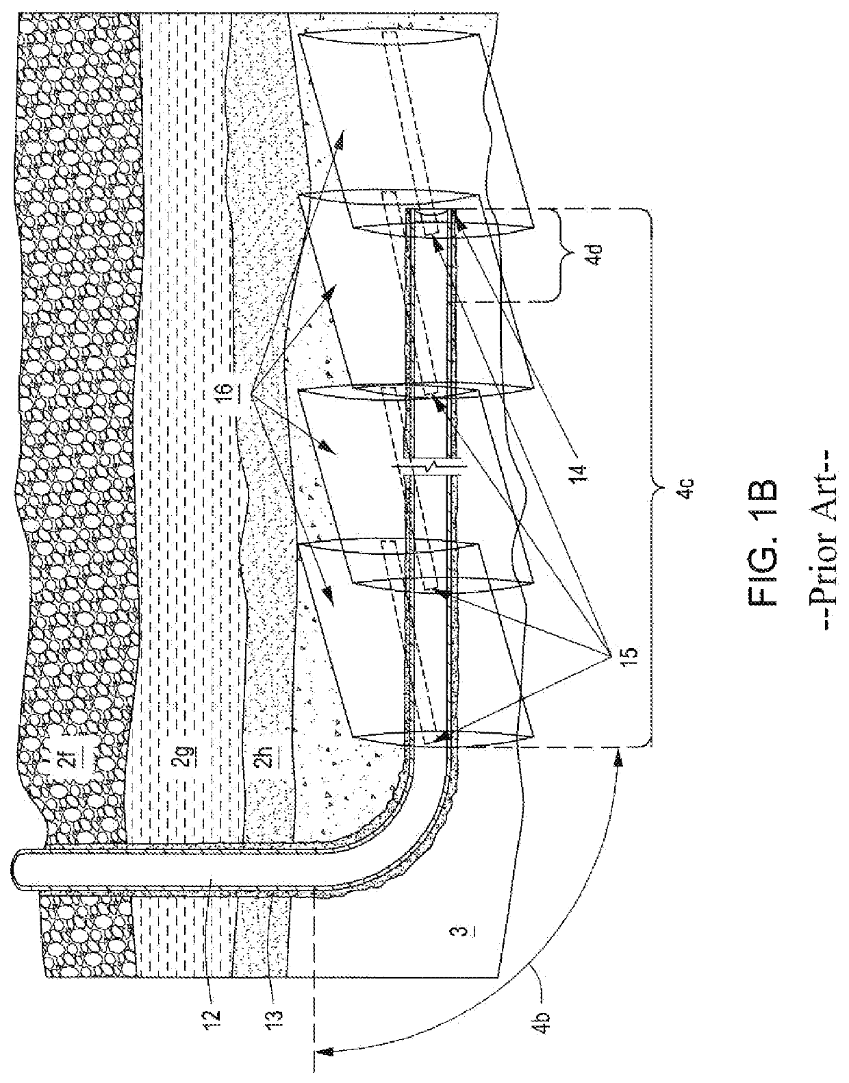
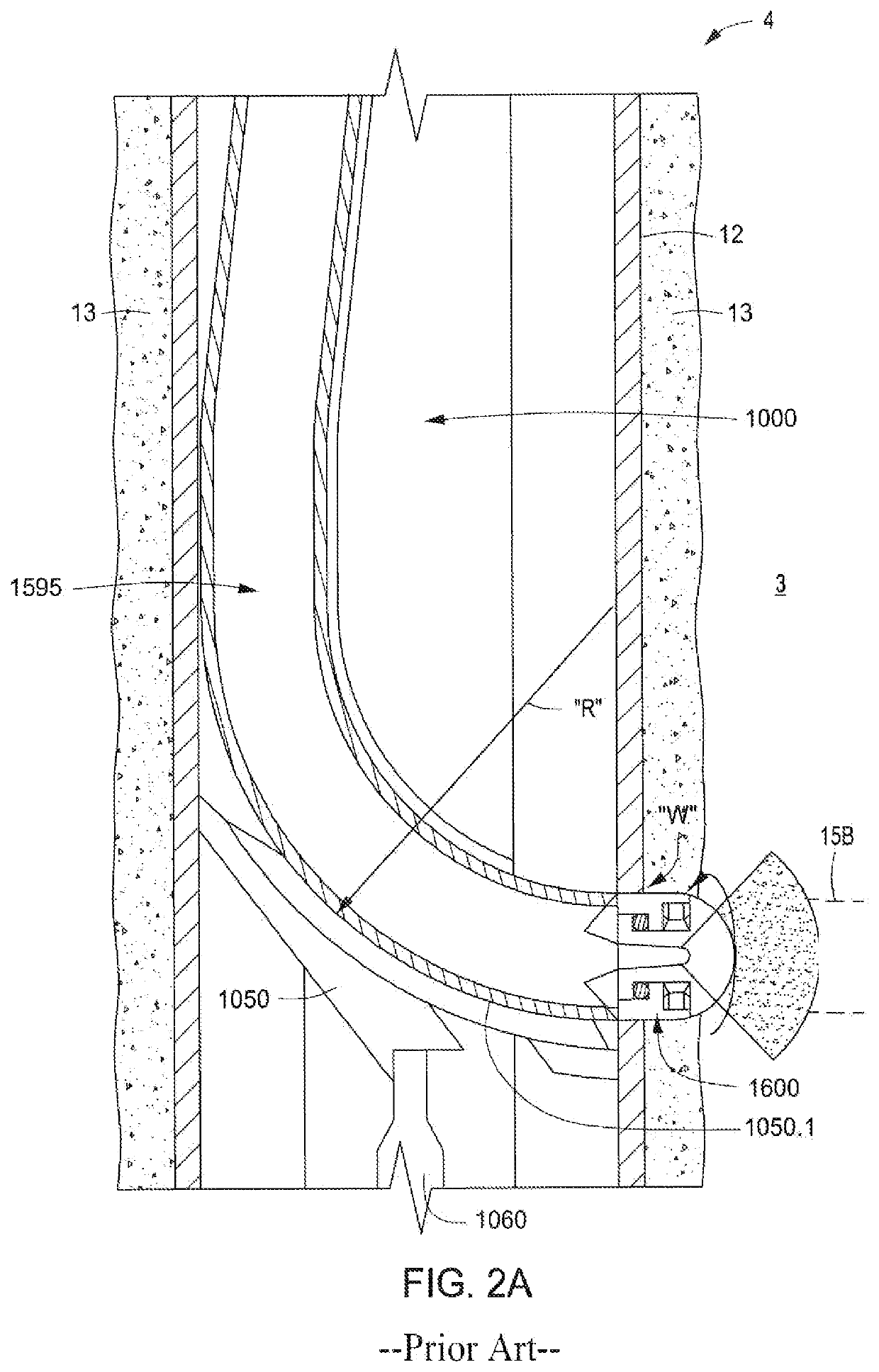
[0090]A downhole apparatus and method of enhancing the range of a whipstock in constructing a mini-lateral borehole (or Ultra Deep Perforation, “UDP”) off of a host wellbore (or borehole) by: (1) dynamically locating the trajectory of a high pressure jetting fluid along a predetermined arcuate path; while, (2) concurrently establishing in situ a temporary, rigid, and enlarged bend radius for the flexible jetting fluid conduit. The curved, rigid, and telescopic aspects of the apparatus both support and guide the distal end of the jetting assembly as it erosionally excavates the arcuate path, first through the well casing (or ported casing collar), then through the well's cement sheath, and finally on out into the subsurface formation (typically, the pay zone).

[0091]The apparatus then serves to encase the initial, curvilinear portion of the UDP, while establishing the final, linear trajectory for the jetting nozzle as the nozzle disengages from the apparatus and advances on out into t...


PUM


Abstract

An apparatus and downhole method for dynamically establishing in situ an arcuate path of up to 90° or more for a jetting hose or other flexible conduit for forming a lateral bore. The apparatus includes a whipstock comprised of one or more arcuate, telescoping segments which enable the operator to avoid the friction pressure and HHP restrictions of smaller diameter hoses, imposed due to the minimum bend radius restrictions encountered when forming the bend radius solely inside the casing of a wellbore. The apparatus can also be used with a Custom Ported Casing Collar. The hose bending path is established immediately behind the jetting nozzle as the lateral borehole is excavated. Upon retrieval of the flexible conduit and excavation device, the arced extension retracts back into the whipstock body, so as not to impede the whipstock's reorientation and / or depth relocation for forming the next mini-lateral.

Description

STATEMENT OF RELATED APPLICATIONS[0001]This application claims the benefit of U.S. Provisional Application Ser. No. 63 / 000,969 filed on Mar. 27, 2020 and incorporates said provisional application by reference into this document as if fully set out at this point.FIELD OF THE INVENTION[0002]The present invention relates to the field of well completion. More particularly, the present invention relates to apparatuses and methods for the completion and stimulation of hydrocarbon-producing or other formations by the generation of smaller diameter boreholes from a parent or main borehole by hydraulic jetting, drilling or other excavation techniques.BACKGROUND OF THE INVENTION[0003]This section is intended to introduce selected aspects of the art, which may be associated with various embodiments of the present disclosure. This discussion is believed to assist in providing a framework to facilitate a better understanding of particular aspects of the present disclosure. Accordingly, it should...

Claims


Application Information

Patent Timeline
Patent Type & Authority Patents(United States)
IPC IPC(8): E21B7/18E21B7/06E21B29/00E21B29/06E21B43/26
CPCE21B7/18E21B7/061E21B29/002E21B29/06E21B43/26
Inventor RANDALL, BRUCE L.RANDALL, BRADFORD G.
Owner COILED TUBING SPECIALTIES
Learn More