Beverage bottling plant for filling bottles with a liquid beverage material having a treatment device for the treatment of bottle caps

a technology for beverage bottling and liquid beverage materials, which is applied in the direction of caps, pretreatment, packaging goods, etc., can solve the problems of helical, affecting the quality of the product, and the complexity of the construction, so as to achieve a long trajectory and low risk of problems.

Inactive Publication Date: 2005-11-10
KHS GMBH
View PDF9 Cites 6 Cited by
  • Summary
  • Abstract
  • Description
  • Claims
  • Application Information

AI Technical Summary

Benefits of technology

[0010] The object is to create a treatment device of the type described above that has a simpler construction and is also less susceptible to malfunctions and jamming.
[0012] The present application teaches that the caps run one after another on a plurality of encircling horizontal carrier rings that are arranged one above the other, are self-propelled and thus transport the caps in a horizontal position over a large rotational angle. In one sector of the device, transfer chutes are located above one another, each of which accepts the caps from a carrier ring and transfers them to the next-lower carrier ring by allowing them to slide downward a short distance. The construction of this device is very simple. It requires essentially a plurality of driven carrier rings that move in synchronization above one another, as well as the stationary transfer chutes. The danger of malfunctions and jams is significantly less than in the construction of the prior art, because with when the caps are transported in the horizontal position on the carrier rings, there is less danger of a malfunction and the risk of problems is very low in the relatively short transfer chutes. The carrier rings can be located one above another essentially at the interval of the cap heights, so that a very long trajectory can be covered in a relatively small housing.
[0015] An additional advantageous feature could be that the carrier rings are driven in synchronization with one another. The construction thereby becomes significantly simpler compared to special constructions that are also possible in the context of this embodiment with individual drives for the carrier rings, which can be realized in the form of individually driven wheels, for example.
[0016] Advantageous features are also disclosed, according to which the carrier rings are fastened one above another to the external cylindrical surface of a revolving drum, which makes possible a very simple construction. The drum can thereby form the internal lateral guide that travels along with the carrier rings and thus further reduces the danger of jamming. The drum offers the additional advantage that it can be realized in the form of a closed drum and can thus form the inner boundary of the space inside the closed housing filled with the treatment atmosphere.

Problems solved by technology

When the track is realized in the form of a chute or a driven conveyor, that can cause significant problems in terms of space and construction.
One disadvantage of this construction is the helical, stationary realization of the trajectory on which the caps move by sliding over the entire length of the trajectory.
The result is an extraordinarily complicated construction which is also susceptible to jams and backups.
The danger of malfunctions and jams is significantly less than in the construction of the prior art, because with when the caps are transported in the horizontal position on the carrier rings, there is less danger of a malfunction and the risk of problems is very low in the relatively short transfer chutes.

Method used


Image

  • Beverage bottling plant for filling bottles with a liquid beverage material having a treatment device for the treatment of bottle caps
  • Beverage bottling plant for filling bottles with a liquid beverage material having a treatment device for the treatment of bottle caps
  • Beverage bottling plant for filling bottles with a liquid beverage material having a treatment device for the treatment of bottle caps

Examples


Embodiment Construction

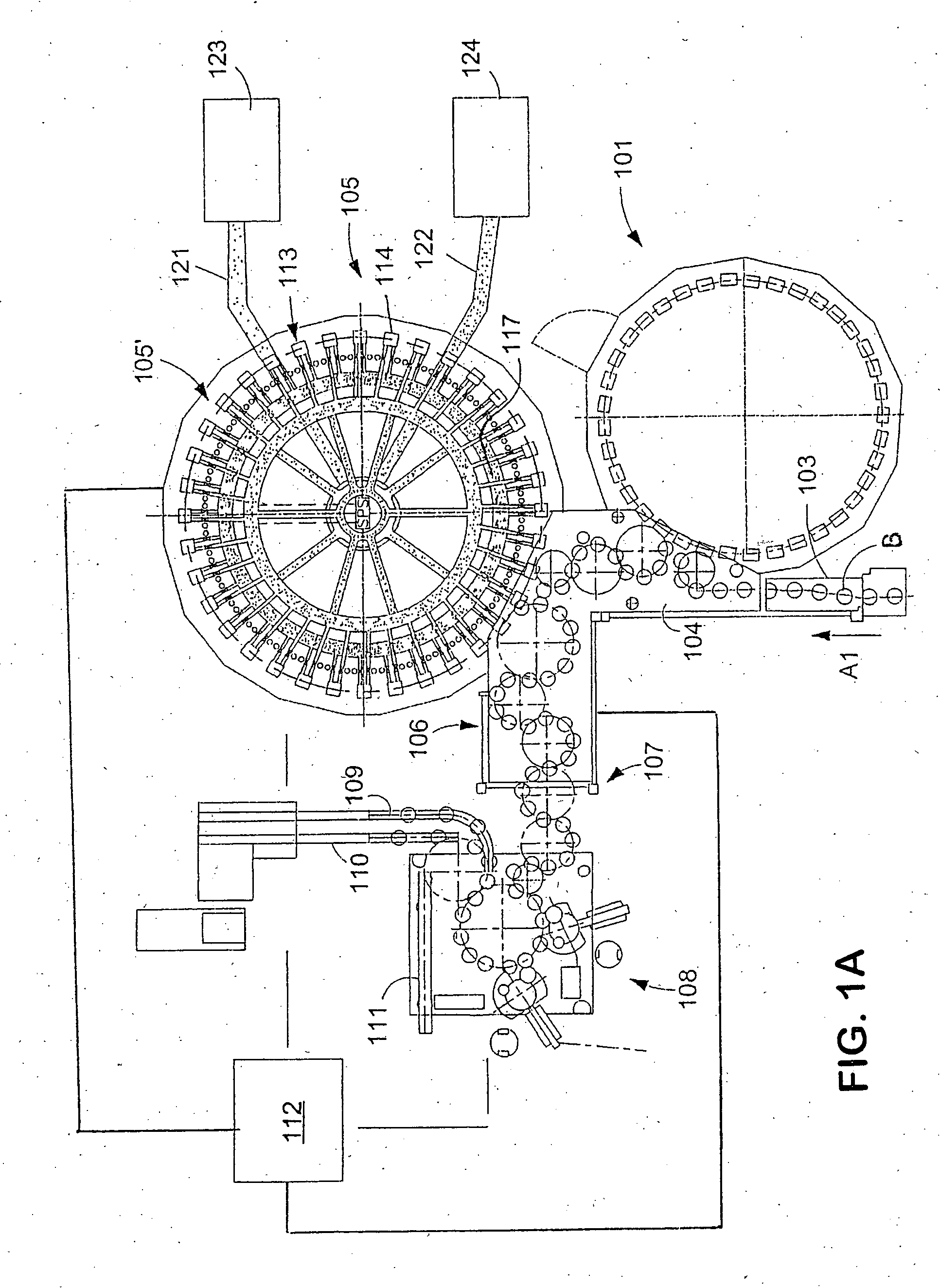
[0026]FIG. 1A shows schematically the main components of one possible embodiment example of a system for filling containers, specifically, a beverage bottling plant for filling bottles B with at least one liquid beverage, in accordance with at least one possible embodiment, in which system or plant could possibly be utilized at least one aspect, or several aspects, of the embodiments disclosed herein.

[0027]FIG. 1A shows a rinsing arrangement or rinsing station 101, to which the containers, namely bottles B, are fed in the direction of travel as indicated by the arrow A1, by a first conveyer arrangement 103, which can be a linear conveyor or a combination of a linear conveyor and a starwheel. Downstream of the rinsing arrangement or rinsing station 101, in the direction of travel as indicated by the arrow A1, the rinsed bottles B are transported to a beverage filling machine 105 by a second conveyer arrangement 104 that is formed, for example, by one or more starwheels that introduc...


PUM

PropertyMeasurementUnit
gas-permeableaaaaaaaaaa
volumeaaaaaaaaaa
timeaaaaaaaaaa

Abstract

A beverage bottling plant for filling bottles with a liquid beverage material having a treatment device for the treatment of bottle caps. The abstract of the disclosure is submitted herewith as required by 37 C.F.R. §1.72(b). As stated in 37 C.F.R. §1.72(b): A brief abstract of the technical disclosure in the specification must commence on a separate sheet, preferably following the claims, under the heading “Abstract of the Disclosure.” The purpose of the abstract is to enable the Patent and Trademark Office and the public generally to determine quickly from a cursory inspection the nature and gist of the technical disclosure. The abstract shall not be used for interpreting the scope of the claims. Therefore, any statements made relating to the abstract are not intended to limit the claims in any manner and should not be interpreted as limiting the claims in any manner.

Description

CONTINUING APPLICATION DATA [0001] This application is a Continuation-In-Part application of International Patent Application No. PCT / EP2003 / 008862, filed on Aug. 9, 2003, which claims priority from Federal Republic of Germany Patent Application No. 102 38 633.1, filed on Aug. 19, 2002. International Patent Application No. PCT / EP2003 / 008862 was pending as of the filing date of this application. The United States was an elected state in International Patent Application No. PCT / EP2003 / 008862.BACKGROUND [0002] 1. Technical Field [0003] The present application relates to a beverage bottling plant for filling bottles with a liquid beverage material having a treatment device for the treatment of bottle caps. [0004] 2. Background Information [0005] A beverage bottling plant for filling bottles with a liquid beverage filling material can possibly comprise a beverage filling machine with a plurality of beverage filling positions, each beverage filling position having a beverage filling devic...

Claims


Application Information

Patent Timeline
Patent Type & Authority Applications(United States)
IPC IPC(8): A61L2/18B65B55/10A61L2/20A61L2/26
CPCA61L2/18B67B3/003A61L2/26A61L2/20
Inventor TOPF, ROLAND
Owner KHS GMBH
Why Eureka
Try Eureka