Oil-gas separation device for air leakage test of engine piston

A technology of piston air leakage and separation device, which is applied in the field of test equipment and oil-gas separation device for engine piston air leakage test. Efficiency, meet the oil and gas separation requirements, increase the effect of the contact area

Inactive Publication Date: 2017-05-31
JILIN UNIV
View PDF7 Cites 0 Cited by
  • Summary
  • Abstract
  • Description
  • Claims
  • Application Information

AI Technical Summary

Problems solved by technology

[0008] The technical problem to be solved by the present invention is to overcome the problems of low oil-gas separation efficiency, complex structure and poor versatility in the prior art, and to provide a universal and high separation efficiency tester for engine piston leakage Oil and gas separation device

Method used


Image

  • Oil-gas separation device for air leakage test of engine piston
  • Oil-gas separation device for air leakage test of engine piston
  • Oil-gas separation device for air leakage test of engine piston

Examples


Embodiment Construction

[0026] The present invention is described in detail below in conjunction with accompanying drawing:

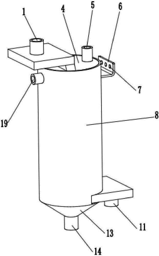
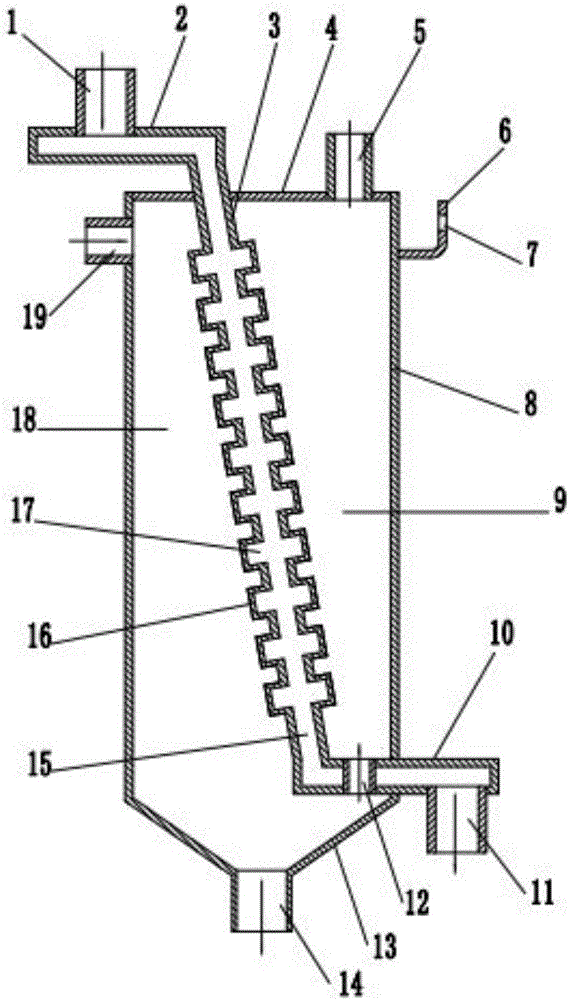
[0027] refer to figure 1 and figure 2 According to the present invention, an oil-air separation device for engine piston air leakage test includes an oil-air separator body 8, a radiator and a cooling water control system.

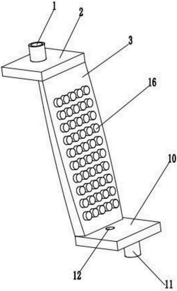
[0028] refer to figure 2 and figure 2 , the oil-gas separator body 8 is a cylindrical shell structure, the top cover 4 of the oil-gas separator body 8 is a circular flat plate, and the right side of the top cover 4 is provided with a cylindrical The oil and gas outlet 5 of the top cover 4 is provided with a through hole for installing the flow cavity 3 in the radiator. The external dimensions at this place are equal. On the left cylinder wall at the upper end of the oil-gas separator body 8, a cylindrical oil-gas inlet 19 connected to the cylinder wall is provided, and a L is welded on the outside of the right cylinder wall opposite to the oil-gas i...


PUM


Abstract

The invention discloses an oil-gas separation device for an air leakage test of an engine piston. According to the oil-gas separation device, the problems of low oil-gas separation efficiency, complex structure and low universality in the prior art are solved. The oil-gas separation device comprises an oil-gas separator body, a heat sink and a cooling water control system, wherein the heat sink is obliquely arranged in the oil-gas separator body, a lower water chamber of the heat sink stretches out of an arc-shaped through hole in a right side cylinder wall of the oil-gas separator body, the upper end of a flow cavity of the heat sink stretches out of the left side of a top cover of the oil-gas separator body, the lower water chamber is in welded connection with the right side cylinder wall of the oil-gas separator body, the upper end of the flow cavity of the heat sink is in welded connection with the left side of the top cover of the oil-gas separator body, and the flow cavity is in welded connection with a contact part on the inner surface of the oil-gas separator body; and an electric two-way valve in the cooling water control system is mounted on a cooling water supply pipe connected with the cooling water tower, and a temperature sensor in the cooling water control system is mounted on a pipeline connected to an oil-gas outlet of the oil-gas separator body.

Description

technical field [0001] The present invention relates to a test device in the field of engine development, more precisely, the present invention relates to a kind of oil and gas separation device used for engine piston leakage test Background technique [0002] 1. When the engine is working, due to the gap between the cylinder liner and the piston and piston ring, a part of the mixed gas containing fuel, oil, water vapor and other vapors will enter the crankcase. If there are defects in the design or processing of pistons, piston rings and cylinder liners, the mixture gas leaking into the crankcase will greatly increase, resulting in reduced engine power, increased fuel consumption, and increased oil consumption. In order to avoid design defects in pistons, piston rings and cylinder liners, and to control the mixture gas entering the crankcase, during the development process of the engine, the piston leakage test must be carried out to establish a test database for evaluating...

Claims


Application Information

Patent Timeline
Patent Type & Authority Applications(China)
IPC IPC(8): G01M15/02B01D53/26
CPCB01D53/265G01M15/02
Inventor 邱森黄华袁兆成顾灿松马家义杨征睿
Owner JILIN UNIV
Why Eureka
Try Eureka