
Dental hand piece

a hand piece and hand technology, applied in dentistry, dental surgery, medical science, etc., can solve the problems of high design complexity of the central and end-side arrangement, inability to axially fix the base body and the hand piece, and high vibration and noise emissions of the hand piece, so as to achieve low cost and simple construction. , the effect of robust operation

Active Publication Date: 2022-09-06
DENTSPLY SIRONA INC
View PDF11 Cites 0 Cited by
  • Summary
  • Abstract
  • Description
  • Claims
  • Application Information

AI Technical Summary

Benefits of technology

[0008]In the case of this hand piece a rigid coupling of the housing to the coupling element is prevented, the design being characterized in particular by its simplicity and effectiveness. It has been found to be sufficient if the vibrations that are introduced by way of the head are damped by means of a resilient decoupling element in the coupling region and if the axial bracing of the housing, which can also be designed as an outer sleeve, is reduced in comparison to a rigid mounting.
[0009]The provision of a resilient releasable connection by means of a strictly springy element or a springy and damping element between the housing and the coupling element in the axial direction, instead of a rigid, releasable connection, requires only a small amount of installation space, and just a few additional single components are necessary. The design is simple in construction, inexpensive in terms of implementation, robust in operation and user friendly in terms of maintenance and repair, while being highly effective at the same time.

Problems solved by technology

If the coupling piece is connected to the grip sleeve in a comparatively rigid manner, then the vibrations and thus the noise emissions are intensified by the grip sleeve as a result.
The drawback with this floating mounting is that the central and end-sided arrangement is highly complex in design.
It is disclosed as an alternative embodiment that elastic elements are provided only on the ends of the grip sleeve; however, these elastic elements do not allow a definite axial fixing between the base body and the grip sleeve.

Method used


Image

  • Dental hand piece
  • Dental hand piece
  • Dental hand piece

Examples


Embodiment Construction

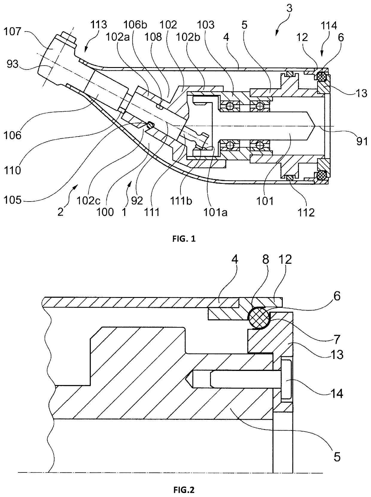
[0025]FIG. 1 shows a dental instrument 1, which is designed as a hand piece and in particular as a contra-angle hand piece. The hand piece 1 comprises a head region 2 with a rotating tool 20 and a coupling region 3 as well as a housing 4, designed as an outer sleeve. The coupling region 3 extends typically over a length of approximately 30% in comparison to the total length of the hand piece 1.

[0026]On the first housing end, located in the coupling region 3, there is provided a coupling element 5, which is designed to be connected to a drive (not shown) and which is braced with respect to the housing 4 by means of a decoupling element 6.

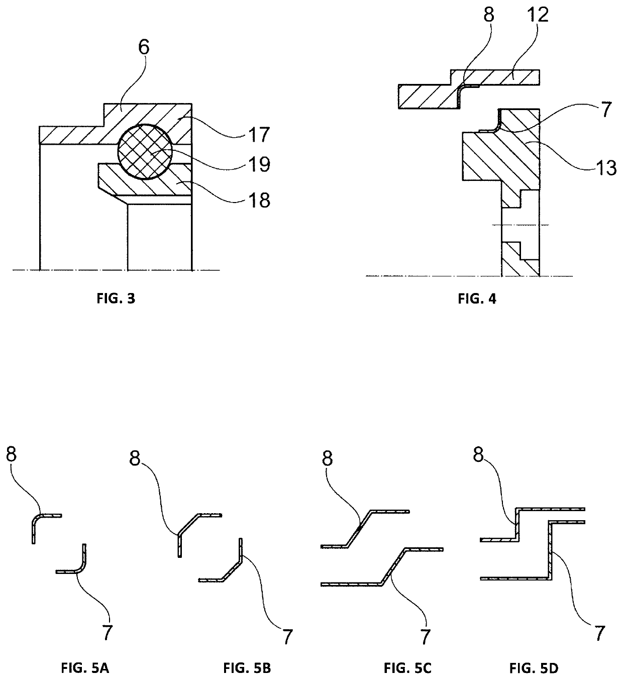
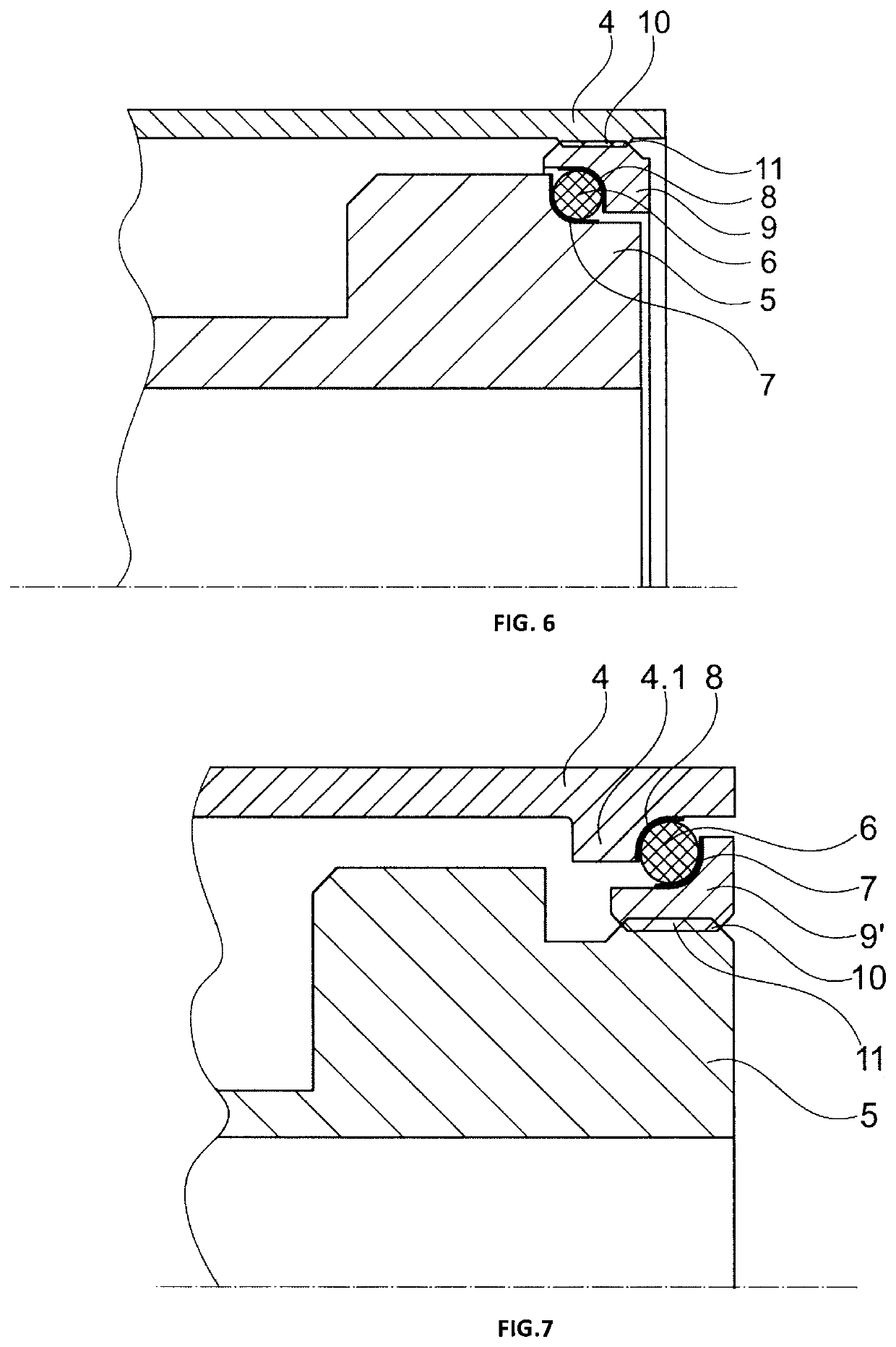
[0027]As shown in detail in FIG. 2, the decoupling element 6 is disposed between a first axial support surface 7 and a second axial support surface 8, wherein the first axial support surface 7 is located on a support ring 12 connected to the outer sleeve, and the second axial support surface 8 is located on a coupling cover 13. The coupling cover 13 ...


PUM


Abstract

Dental hand piece, comprising a housing and a drive train with a coupling element for a drive, wherein the housing radially surrounds the drive train and wherein the housing has a first and a second housing end, and wherein the housing is held on the drive train on the first and on the second housing end. Between the first housing end and the coupling element is arranged a decoupling element, which is strictly springy or springy and damping in the axial direction, whereas the second housing end is braced rigidly against the drive train and the housing is braced with respect to the coupling element in the axial direction by means of the decoupling element.

Description

[0001]The present disclosure relates to a dental hand piece, in particular, a contra-angle hand piece; and, in particular, to the design of such a dental instrument in the area of a coupling end with a drive. Dental instruments have the task of driving a tool, secured in the head region, at high speed. In so doing, the rotating components of dental instruments generate vibrations that are emitted through the outside of the dental instrument. These vibrations can be amplified or attenuated as a function of the embodiment.PRIOR ART[0002]The prior art discloses a variety of approaches, the objective of which is to reduce noise emissions. For example, it is possible to counteract the generation of vibrations by optimizing the mounting of the rotating parts. Even an increase in the mass, in particular an outer sleeve, can reduce the vibration amplitudes and thus result in a noise reduction.[0003]A dental hand piece known from the document EP 0 282 752 A1 comprises a tool that can be driv...

Claims


Application Information

Patent Timeline
Patent Type & Authority Patents(United States)
IPC IPC(8): A61C1/12A61C1/18A61C1/06
CPCA61C1/12A61C1/185A61C1/06
Inventor ERTUGRUL, METINGOBEL, STEFAN
Owner DENTSPLY SIRONA INC
Learn More