
Transflexion probe and transflective sensor

a technology of transflective sensor and probe, which is applied in the field of transflective probe, can solve the problems of high optical loss, low measurement sensitivity owing to high optical loss, and high loss in the fiber material,

Active Publication Date: 2014-03-13
SARTORIUS STEDIM BIOTECH GMBH
View PDF5 Cites 3 Cited by
  • Summary
  • Abstract
  • Description
  • Claims
  • Application Information

AI Technical Summary

Benefits of technology

The invention is about a device that allows for the safe and efficient coupling of a sensor module to a hollow probe shaft. The device allows for the free beam guidance of light through the probe shaft, while also allowing for the simple replacement of sensor modules on the same or different probes. Additionally, the device includes a parabolic mirror that collimates the light and prevents aberrations, making it easier to transport light through the probe shaft. The technical effects of this invention are improved safety and efficiency in the coupling of sensor modules to hollow probe shafts.

Problems solved by technology

The low measurement sensitivity owing to high optical losses is a disadvantage in the case of the known instrument.
Also, it is particularly the case that the near infrared region is a spectral region of electromagnetic waves which it is difficult to transmit by means of optical fibers.
Here, high losses in the fiber material and, in particular, in bends of the fibers occur.
However, this leads to an increased energy consumption and to thermal problems in the spectrometer unit.

Method used


Image

  • Transflexion probe and transflective sensor
  • Transflexion probe and transflective sensor

Examples


Embodiment Construction

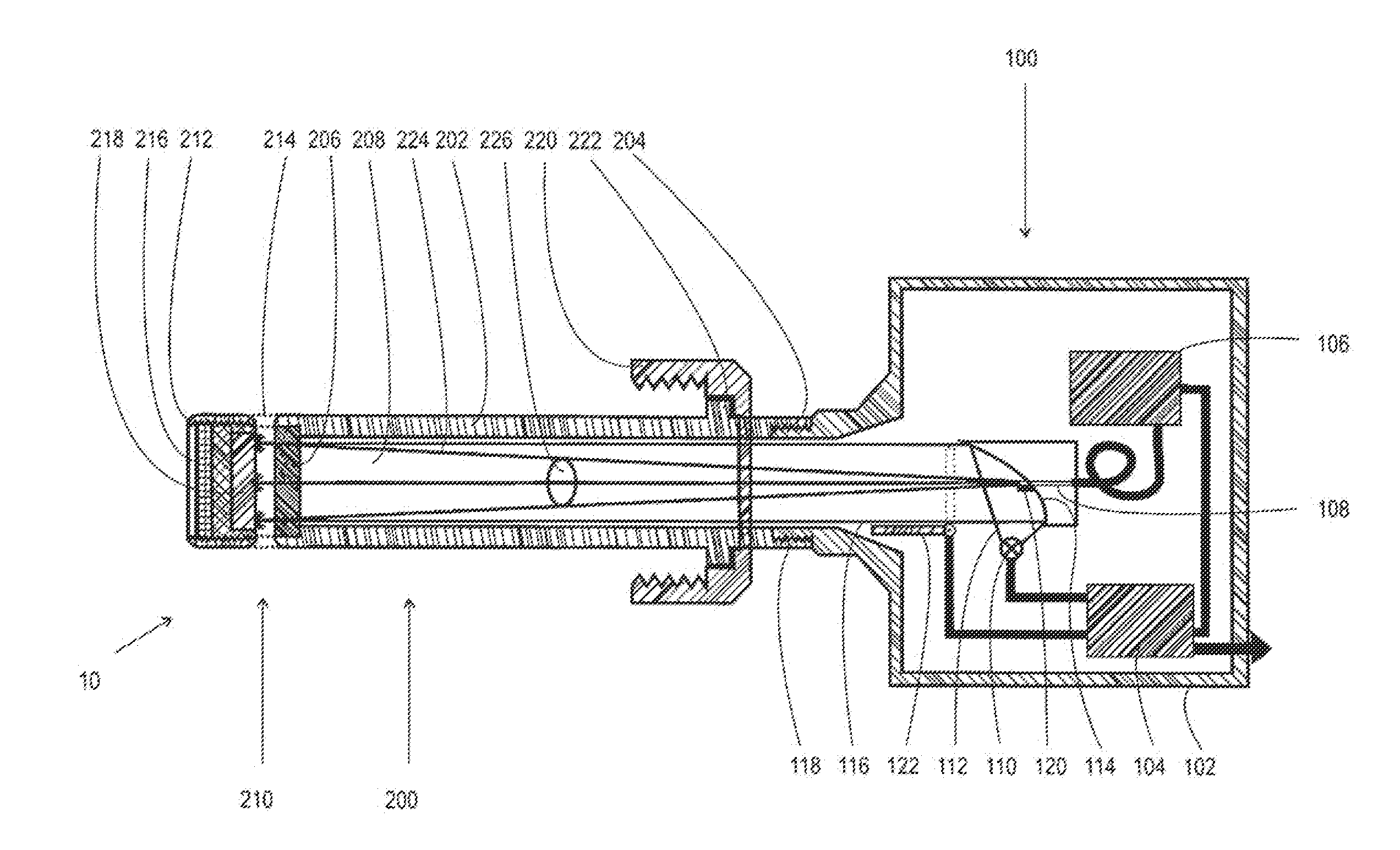
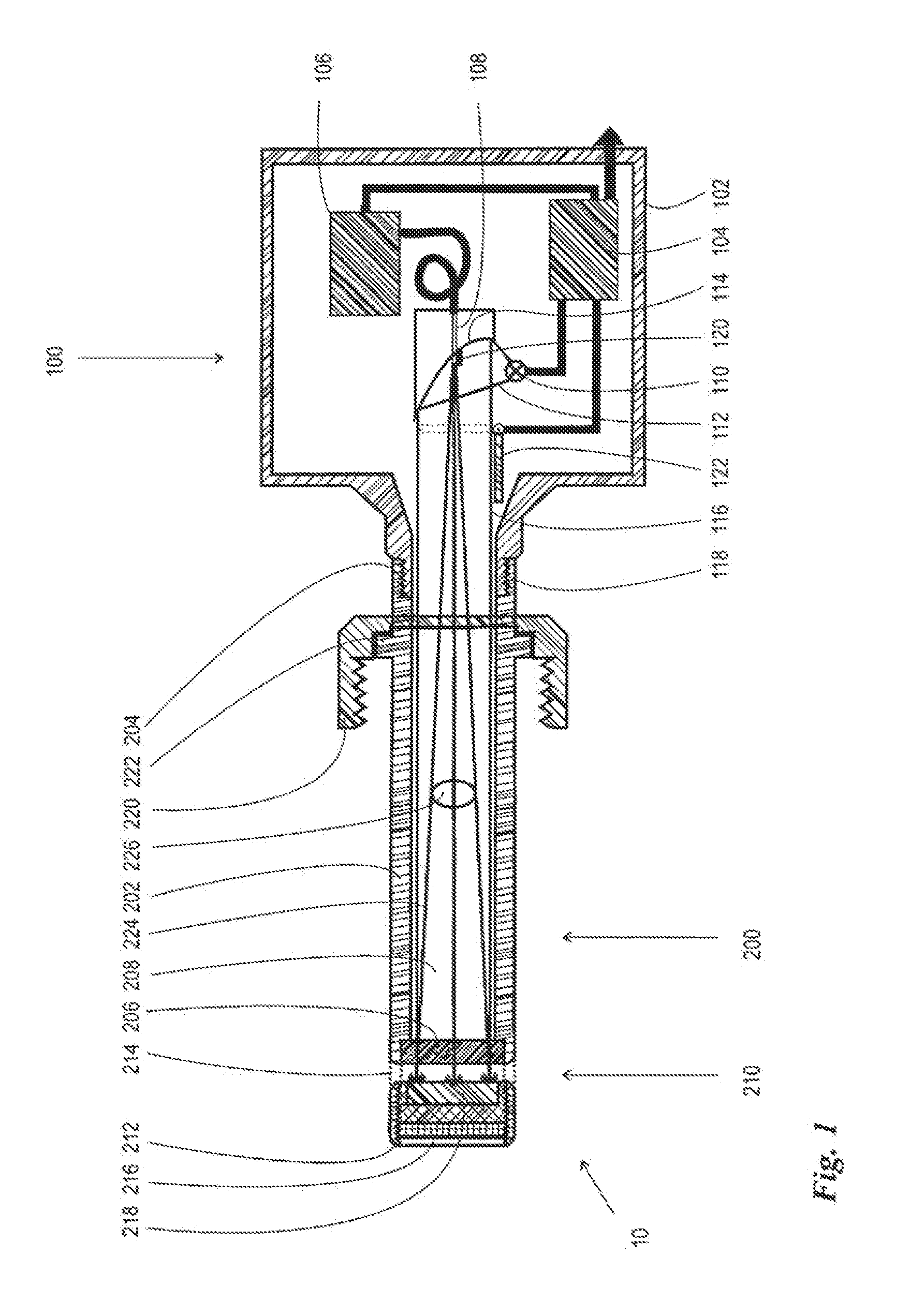
[0023]FIG. 1 shows a sectional schematic of an inventive transflective sensor 10. The transflective sensor 10 comprises two main units, specifically a sensor module 100 and a transflexion probe 200 which is rigidly coupled at its rear end to the sensor module 100 and is adjoined at its front end by a flow chamber 210.

[0024]Inside the housing 102, the sensor module 100 of the embodiment shown has a plurality of units which are not shown in more detail. These are, in particular, a power supply unit 104, which can also be combined with a control unit, and the interface between the sensor module 100 and further units of an installation configured to be as complex as desired. Also shown, purely schematically, is an optical detector 106, which, for example, can be designed as a spectrometer, in particular as an NIR spectrometer, but can also be designed in a different way, for example as a photodiode or as some other type of optical detector. In the embodiment illustrated, the optical inp...


PUM


Abstract

The invention comprises a transflexion probe for carrying out a transflexion measurement on a liquid located in a vessel, comprising a probe shaft (202) which is provided with a light guide path in its interior and at whose front end face there is arranged an open flow chamber (210) with a reflective plate (218) opposite the front end face of the probe shaft (202). The invention is distinguished by the fact that the probe shaft (202) is designed as a rigid cavity which is sealed at its front end face by a transparent window (206) and has at its rear end a first coupling device (204) for the rigid coupling of a sensor module (100) to the probe shaft (202).

Description

BACKGROUND[0001]1. Field of the Invention[0002]The invention relates to a transflexion probe for carrying out a transflexion measurement on a liquid located in a vessel, comprising a probe shaft which is provided with a light guide path in its interior and at whose front end there is arranged an open flow chamber with a reflective plate opposite the front end face of the probe shaft. The invention further relates to a transflective sensor comprising a transflexion probe of the afore-named type and a sensor module coupled thereto.[0003]2. Description of the Related Art[0004]Transflexion probes and transflective sensors are known from Tosi, S. et al.: “Assessment of In-line Near-Infrared Spectroscopy for Continuous Monitoring of Fermentation Processes”, Biotechnol. Prog. 2003, 19, 1816-1821. This printed publication describes a sensor based on spectroscopic measurements in the near infrared region for the purpose of monitoring a culture liquid in a bioreactor. The sensor is assembled ...

Claims


Application Information

Patent Timeline
IPC IPC(8): G01N21/85
CPCG01N21/85G01N21/359G01N21/8507G01N2021/8521
Inventor RIECHERS, DANIELGRIMM, CHRISTIAN
Owner SARTORIUS STEDIM BIOTECH GMBH
Learn More