
Laser machining head

a laser machining and head technology, applied in the direction of auxillary welding devices, soldering apparatus, instruments, etc., can solve the problems of affecting the quality of the soldering head, so as to achieve rapid and simple replacement of the optics

Active Publication Date: 2018-12-11
PRECITEC GMBH
View PDF20 Cites 0 Cited by
  • Summary
  • Abstract
  • Description
  • Claims
  • Application Information

AI Technical Summary

Benefits of technology

[0013]Thus, the invention is based on the object of devising a laser machining head with optics held displaceably therein, in which contamination of the optics can largely be avoided and the optics can be held securely in their adjusted position, even if high inertial forces occur as a result of high accelerations.
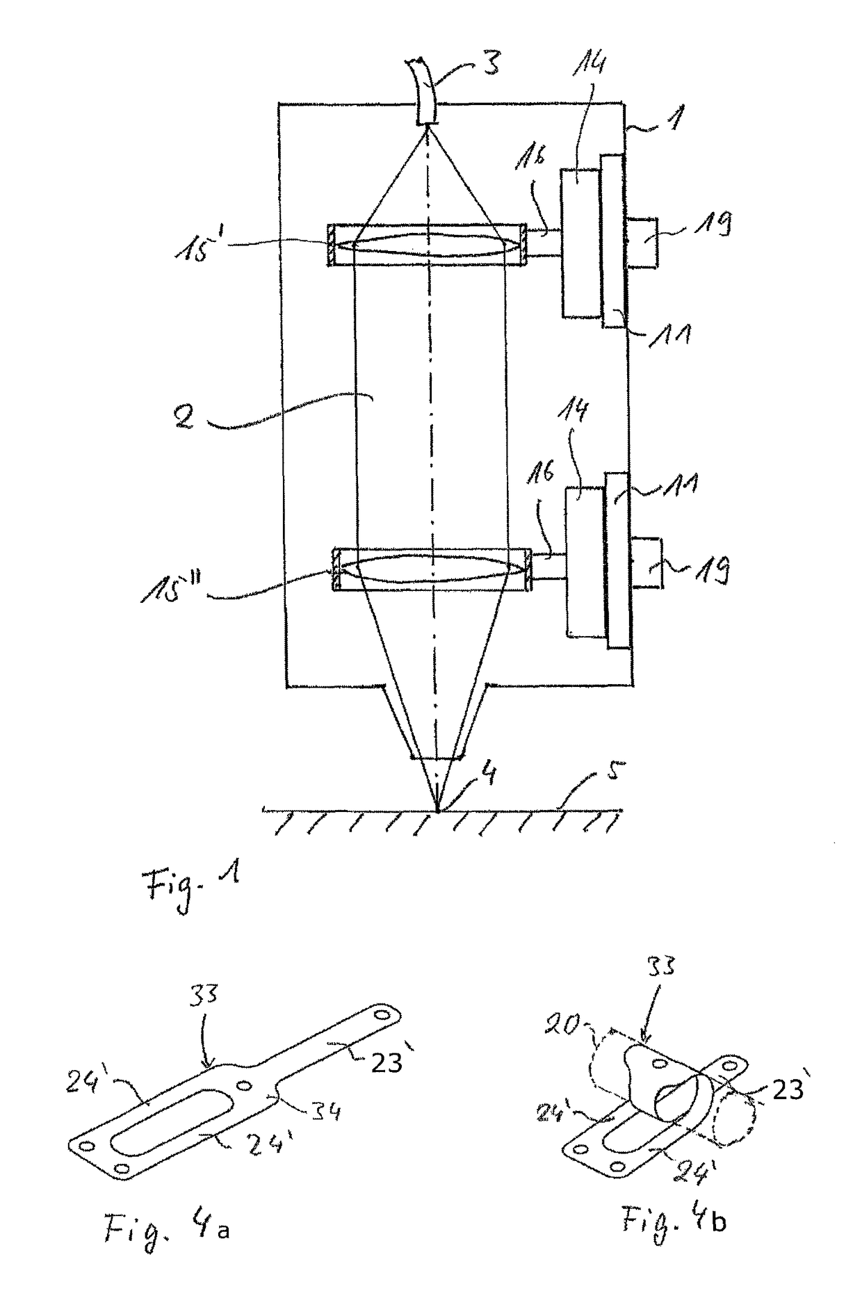
[0015]According to the invention, therefore, a laser machining head for holding and displacing beam-shaping optics, such as focusing optics for focusing a laser beam onto a workpiece, collimator optics, which are mounted on the slide-in unit such that they can be displaced in the longitudinal direction of the laser beam, or zoom optics, has a belt drive with which the beam-shaping optics can be displaced precisely and which keeps beam-shaping optics securely in the adjusted position even if high inertial forces occur as a result of rapid movements and speed changes of the laser machining head. The belt drive provided in accordance with the invention has the advantage that, during the displacement of the optics, no sliding friction which could lead to abrasion occurs in the belt drive; instead only rolling friction, so that contaminants such as could occur in the prior art are avoided.
[0023]Furthermore, it is expedient for the mounting for supporting the optics that can be displaced in the longitudinal direction of the laser beam to be held on a slide-in unit which can be inserted into the laser machining head. In this way, rapid and simple replacement of the optics can be made possible, if this becomes necessary because of a change of focal length or damage to the optics.

Problems solved by technology

In this case, it is disadvantageous that, even with a cable diameter of only about 1 mm and bending radii of about 20 mm within the cable, abrasion is produced by friction between the individual wires.
As a result, the interior of a machining head and in particular the optics therein can be contaminated.
The disadvantage here is that the optics can be moved in an undesired manner and thus the focal position can be shifted if high accelerations act on the direct drive from outside, since then inertial forces can occur, which can be greater than the magnetic holding force.
However, as is known, this type of drive is sluggish and relatively inaccurate on account of the spontaneous play of the worm drive.

Method used


Image

  • Laser machining head
  • Laser machining head

Examples


Embodiment Construction

[0030]In the various figures of the drawing, mutually corresponding components are provided with the same designations.

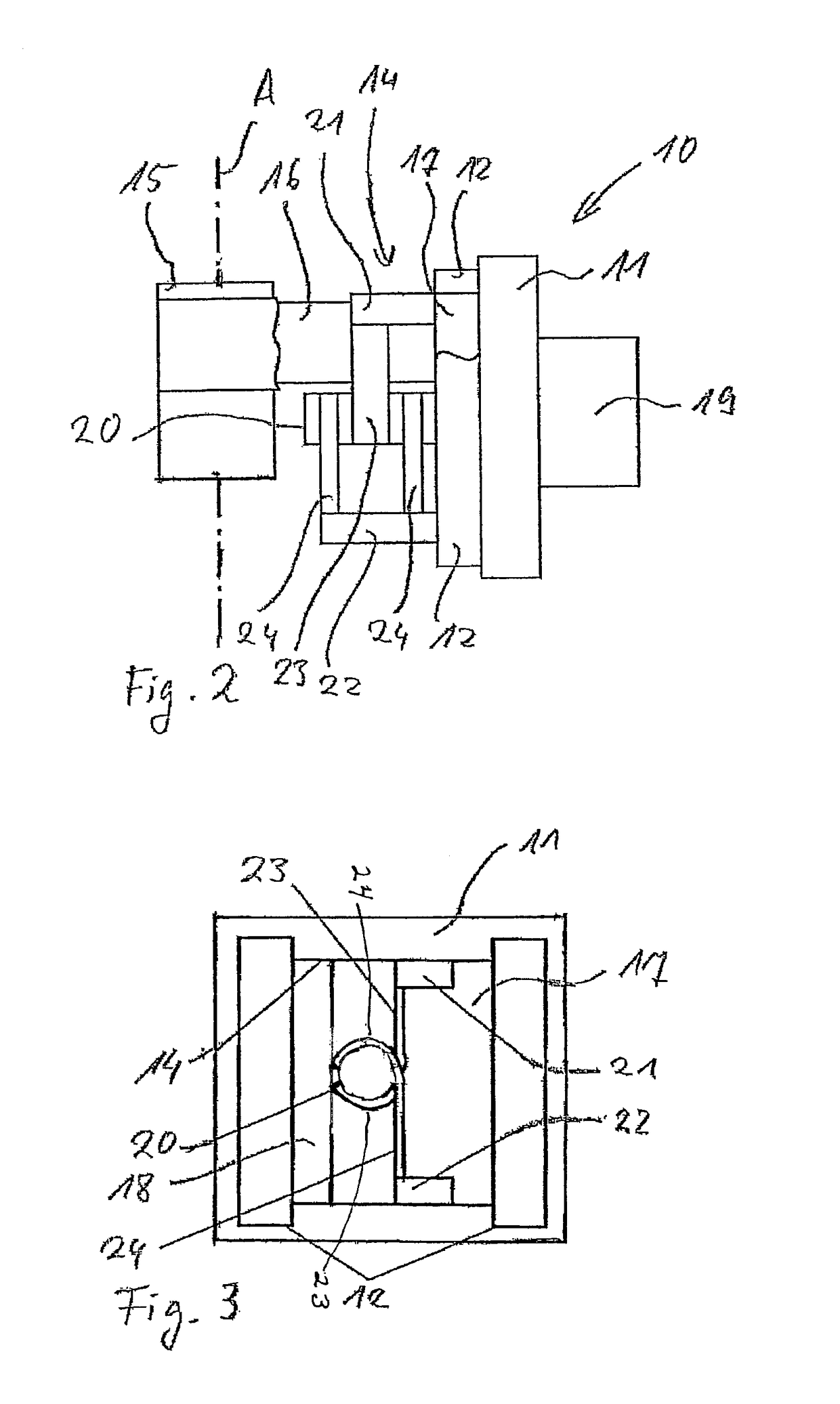
[0031]As illustrated in FIG. 1, a laser machining head according to the invention has a housing 1, through which a laser beam 2 is led. In order to shape the laser beam 2 emerging from an optical fiber 3, for example, first optics 15′, which are formed as collimator optics, and second optics 15″ are provided, which as focusing optics focus the laser beam 2 into the interaction area 4 between laser beam 2 and workpiece 5. For the displaceable mounting of the optics 15′, 15″, the latter are respectively fixed via a holder 16 to a carriage 14 of a belt drive, which can be driven by a motor 19 and is displaceably guided on a mounting 11. The mounting 11 can be fixed directly in the housing 1 of the laser machining head, as illustrated in FIG. 1. However, it is also possible—as shown in FIG. 2—to provide the mounting 11 on a slide-in unit 10, which can be inserted into t...


PUM

PropertyMeasurementUnit
thicknessaaaaaaaaaa
thicknessaaaaaaaaaa
thicknessaaaaaaaaaa

Abstract

A laser machining head for machining a workpiece with a laser beam, having a mounting, beam-shaping optics, which are mounted on the mounting such that they can be displaced in the longitudinal direction of the laser beam. In order largely to avoid contamination of the optics and in order to hold the optics securely in their adjusted position, even if high inertial forces occur as a result of higher accelerations, a belt drive is provided for displacing the optics.

Description

BACKGROUND OF THE INVENTION[0001]Field of the Invention[0002]The invention relates to a laser machining head, in which beam-shaping optics, in particular focusing optics, collimator optics or zoom optics, are displaceably or adjustably held.[0003]Brief Description of the Related Art[0004]During the machining of a workpiece by means of a laser machining head, in particular during laser cutting or welding, a laser machining head is usually provided with a housing in which focusing optics, collimator optics, zoom optics or are arranged. A laser beam running through the laser machining head to a cutting nozzle is focused by focusing optics such that a workpiece can be machined. The optics for shaping the laser beam are held in the laser machining head in this context such that the optics are adjustable relative to the housing of the laser machining head. Here, the optics can be adjusted firstly in a plane perpendicular to the laser beam and secondly in the longitudinal direction of the ...

Claims


Application Information

Patent Timeline
Patent Type & Authority Patents(United States)
IPC IPC(8): B23K26/064G02B7/04B23K26/04B23K26/14B23K26/70G02B7/10B23K26/06
CPCB23K26/064B23K26/04B23K26/048B23K26/06G02B7/102B23K26/1476B23K26/702G02B7/04B23K26/0665B23K26/08B23K37/02
Inventor SPOERL, GEORGLOOSE, CHRISTIAN
Owner PRECITEC GMBH
Learn More