Energy meter circuit for short and low-intensity laser pulses

a technology of energy meter and laser pulse, which is applied in the direction of optical radiation measurement, instruments, active medium materials, etc., can solve the problems of laser energy meter damage, false reading and high cost of laser energy meter for a wide range of wavelengths

Active Publication Date: 2022-09-06
KING FAHD UNIVERSITY OF PETROLEUM AND MINERALS
View PDF7 Cites 0 Cited by
  • Summary
  • Abstract
  • Description
  • Claims
  • Application Information

AI Technical Summary

Benefits of technology

[0007]In another exemplary embodiment, a system for measuring excitation and ionization of a reactant is disclosed. The system includes a supersonic molecular beam source configured to cool molecules of the reactant to a low vibration state; a dye laser configured to transmit pulses of excitation energy into the reactant; a neodymium-doped yttrium aluminum garnet (ND:YAG) laser configured to transmit pulses of ionization energy into the reactant, wherein the pulses of ionization energy are delayed with respect to the pulses of excitation energy, and the pulses of ionization energy are collinear with the pulses of excitation energy; a pyroelectric detector head configured to receive the pulses of excitation energy and the pulses of ionization energy and generate current pulses proportional to the pulses of excitation energy and the pulses of ionization energy; a laser energy meter circuit including: an amplifier having a first amplifier input and an amplifier output, wherein the first amplifier input is connected to the pyroelectric detector head and is configured to receive the current pulses, and wherein the amplifier output is configured to generate amplified voltage pulses; a sample-and-hold circuit having a first sample-and-hold input connected to the amplifier output to receive the amplified voltage pulses, wherein the sample-and-hold circuit is configured to charge a hold capacitor to a maximum pulse voltage with the amplified voltage pulses; a trigger circuit connected to a second sample-and-hold input, wherein the trigger circuit is configured to receive a transistor-to-transistor logic (TTL) signal and generate a delayed output pulse, Q1 and a trigger signal, Q2; a sample-and-hold circuit output configured to output the maximum pulse voltage when the trigger signal is received at the second sample-and-hold input; a switched capacitor bank connected to the sample-and-hold circuit output; and a peak detector circuit connected to the switched capacitor bank, wherein the peak detector circuit is configured to measure a magnitude of the maximum pulse voltage and generate an averaged DC

Problems solved by technology

Aforementioned laser energy meters for a wide range of wavelengths are expensive.
Also, the existing laser energy meter only measures the laser energy

Method used


Image

  • Energy meter circuit for short and low-intensity laser pulses
  • Energy meter circuit for short and low-intensity laser pulses
  • Energy meter circuit for short and low-intensity laser pulses

Examples


Embodiment Construction

[0019]In the drawings, like reference numerals designate identical or corresponding parts throughout the several views. Further, as used herein, the words “a,”“an” and the like generally carry a meaning of “one or more,” unless stated otherwise.

[0020]Furthermore, the terms “approximately,”“approximate,”“about,” and similar terms generally refer to ranges that include the identified value within a margin of 20%, 10%, or preferably 5%, and any values therebetween.

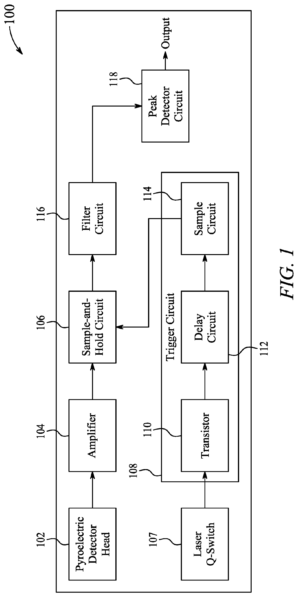
[0021]Aspects of this disclosure are directed to an energy meter circuit and a system for measuring excitation and ionization of a reactant.

[0022]In the present disclosure, the term “connected”, “connected to” and “electrically connected” refer to physical connection between components by any one of wires, buses, contact pads, solder, and pins.

[0023]The energy meter circuit of the present disclosure is configured to measure short and low-intensity laser pulses. The energy meter circuit is configured to be used with a pyroelec...


PUM


Abstract

A laser energy meter circuit, method, and system for measuring excitation and ionization of a reactant. The laser energy meter circuit includes a pyroelectric detector head configured to receive laser pulses and output current signals; an amplifier having a first amplifier input and an amplifier output configured to generate amplified voltage signals; a sample-and-hold circuit; a trigger circuit connected to a second sample-and-hold input, wherein the trigger circuit is configured to receive a TTL signal and generate a delayed output pulse, Q1 and a trigger signal, Q2; a sample-and-hold circuit output configured to output the maximum pulse voltage when the trigger signal is received at the second sample-and-hold input; a switched capacitor bank connected to the sample-and-hold circuit output; and a peak detector circuit configured to measure a magnitude of the maximum pulse voltage and generate an averaged DC maximum pulse voltage signal.

Description

BACKGROUNDTechnical Field[0001]The present disclosure is directed to an energy meter circuit for short and low-intensity laser pulses.Description of Related Art[0002]The “background” description provided herein is for the purpose of generally presenting the context of the disclosure. Work of the presently named inventors, to the extent it is described in this background section, as well as aspects of the description which may not otherwise qualify as prior art at the time of filing, are neither expressly or impliedly admitted as prior art against the present invention.[0003]Laser spectroscopy is used for determining the elemental composition of materials. Laser spectroscopy requires an accurate measurement of laser energy for excitation and ionization of molecules of a sample under study. Based on the measurements, various properties of the sample can be determined. Laser spectroscopy employs a synchronized use of pump (excitation) laser pulses, and probe (ionization) laser pulses. ...

Claims


Application Information

Patent Timeline
IPC IPC(8): H01S3/00G01J5/10H01S3/11H01S3/20H01S3/16H01S3/091H01S3/092
CPCG01J5/10H01S3/0014H01S3/092H01S3/0912H01S3/11H01S3/1611H01S3/1643H01S3/20H01S3/0092H01S3/094034H01S3/115H01S3/2391H01S3/10038G01J5/025G01J5/12G01J5/34G01J1/4257G01J1/0219G01J2001/4238
Inventor GASMI, KHALED
Owner KING FAHD UNIVERSITY OF PETROLEUM AND MINERALS
Why Eureka
Try Eureka