Wireless power smart door lock

a smart door lock and wireless technology, applied in the field of door lock systems, can solve the problems of inconvenient charging, large environmental pollution, and large inconvenience to the daily intelligent switching operation of the lock body, and achieve the effects of reducing the risk of theft, and reducing the safety of charging

Active Publication Date: 2022-09-13
LI PINGCHUAN
View PDF22 Cites 1 Cited by
  • Summary
  • Abstract
  • Description
  • Claims
  • Application Information

AI Technical Summary

Benefits of technology

[0014]Compared with the related art, the technical solution has the following advantages:
[0015]1. The wireless power emitting control device is disposed on the door frame, the wireless power receiving device is disposed on the door body, and the power information interaction between the two devices, the door body state detecting unit acquires the switch state information of the door body in real time, so that the energy storage unit in the lock body can be charged when the door body is closed, and the energy storage unit is always fully charged to ensure the normal operation of the lock body, which greatly improves the operation convenience of the smart lock.
[0016]2. The wireless power emitting control device and the wireless power receiving device cooperate to wirelessly charge without electrical contact, namely a contactless charging method, which is more convenient and safe.

Problems solved by technology

The discarded battery brings great pollution to the environment; if the battery power is exhausted and it is not replaced timely, and the door is locked again, it needs to be restored by external power supply to open the door or open the door in other ways, which brings great inconvenience to the daily intelligent switching operation of the lock body.
Secondly, if external power supply is required, it requires electrical contact to supply power, charging is inconvenient and unsafe.

Method used


Image

  • Wireless power smart door lock
  • Wireless power smart door lock
  • Wireless power smart door lock

Examples


Embodiment Construction

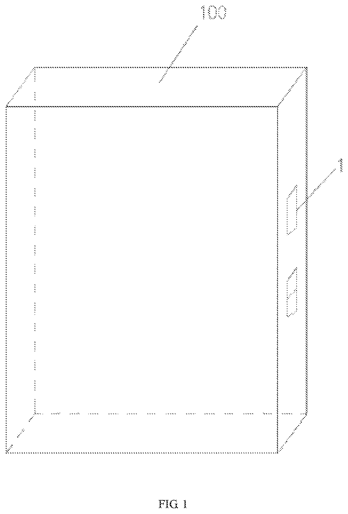
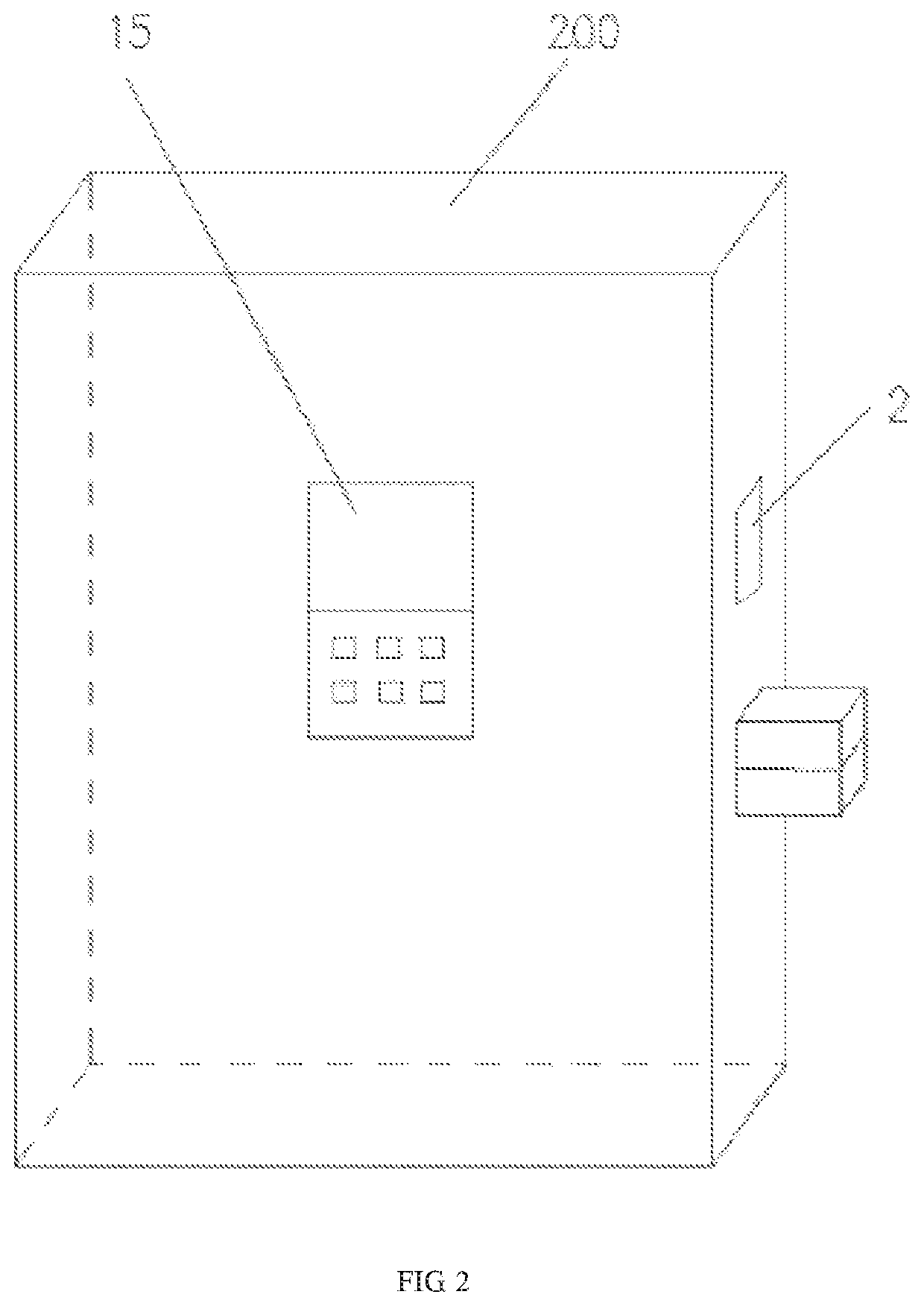
[0023]Referring to FIGS. 1-4, a wireless power supply smart door lock comprises a wireless power emitting control device 1 mounted on a door frame 100 and a wireless power receiving control device 2 mounted on the door body 200.

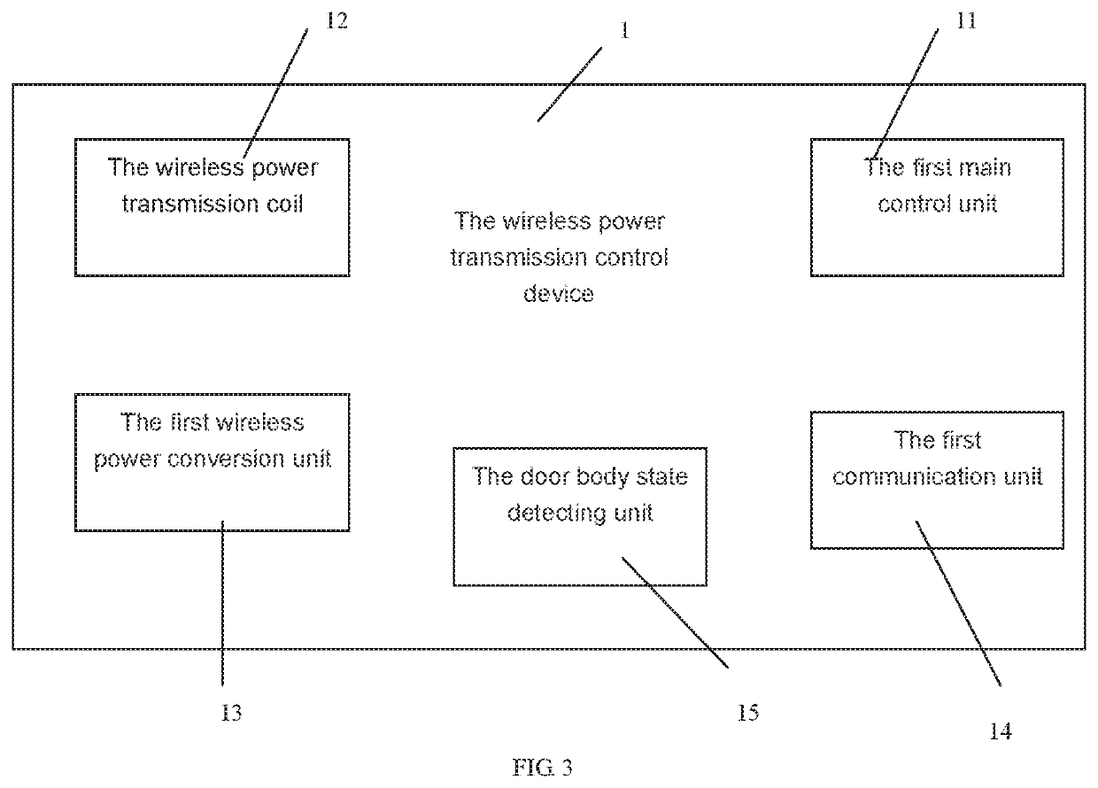
[0024]The wireless power emitting control device 1 comprises a first main control unit 11 and a wireless power emitting coil 12, a first wireless power conversion unit 13, a first communication unit 14 and a door body state detecting unit 15 electrically connected to the first main control unit 11;

[0025]The wireless power receiving control device 2 comprises a second main control unit 21 and a wireless power receiving coil 22, a second wireless power conversion unit 23, an energy storage unit 24 and a second communication unit 25 electrically connected to the second main control unit 21;

[0026]In this embodiment, the door frame 100 specifically refers to the inner position of the door frame, and the door body 200 specifically refers to the side position of the...


PUM


Abstract

Disclosed is a wireless power supply smart door lock, comprising: a wireless power transmission control device mounted on a door frame; the wireless power transmission control device comprises a first main control unit and a wireless power transmission coil, a first wireless power conversion unit, a first communication unit and a door body state detecting unit electrically connected to the first main control unit; the wireless power receiving control device comprises a second main control unit and a wireless power receiving coil, a second wireless power conversion unit, an energy storage unit and a second communication unit electrically connected to the second main control unit; the first main control unit detects the acquired door opening or closing state information and the energy storage unit electric quantity information obtained by the communication interaction in real time according to the door body state detecting unit, and determines whether to trigger the wireless power transmission coil to transmit electric energy to the wireless power receiving coil to charge the energy storage unit. The energy storage unit in the lock body can be charged when the door body is closed, and the energy storage unit is always fully charged to ensure the normal operation of the lock body, which greatly improves the operation convenience of the smart lock.

Description

TECHNICAL FIELD[0001]The present invention relates to a door lock system, in particular to a wireless power supply smart door lock.RELATED ART[0002]The existing smart door locks basically have their own battery power supply. It is necessary to pay attention to the battery power situation at all times. If the battery is wearing out, the battery needs to be replaced. The discarded battery brings great pollution to the environment; if the battery power is exhausted and it is not replaced timely, and the door is locked again, it needs to be restored by external power supply to open the door or open the door in other ways, which brings great inconvenience to the daily intelligent switching operation of the lock body. Secondly, if external power supply is required, it requires electrical contact to supply power, charging is inconvenient and unsafe.SUMMARY OF THE INVENTION[0003]The present invention is provided with a smart lock, which overcomes the disadvantages of the existing known tech...

Claims


Application Information

Patent Timeline
Patent Type & Authority Patents(United States)
IPC IPC(8): E05B47/00E05B49/00
CPCE05B47/0002E05B49/006E05B2047/0068E05B47/0001E05B49/00E05B2047/0057E05B2047/0061E05B47/00
Inventor LI, PINGCHUANMA, PENGCHEN, XIAOSHUN
Owner LI PINGCHUAN
Why Eureka
Try Eureka