Terminal apparatus for transmitting data using uplink grants
a technology of data transmission and uplink grant, applied in the direction of electrical equipment, wireless communication, etc., can solve the problems of increasing the amount of control information, using scheduled access, and mmtc implementation, and achieve the effect of high reliability of data transmission
- Summary
- Abstract
- Description
- Claims
- Application Information
AI Technical Summary
Benefits of technology
Problems solved by technology
Method used
Image
Examples
first embodiment
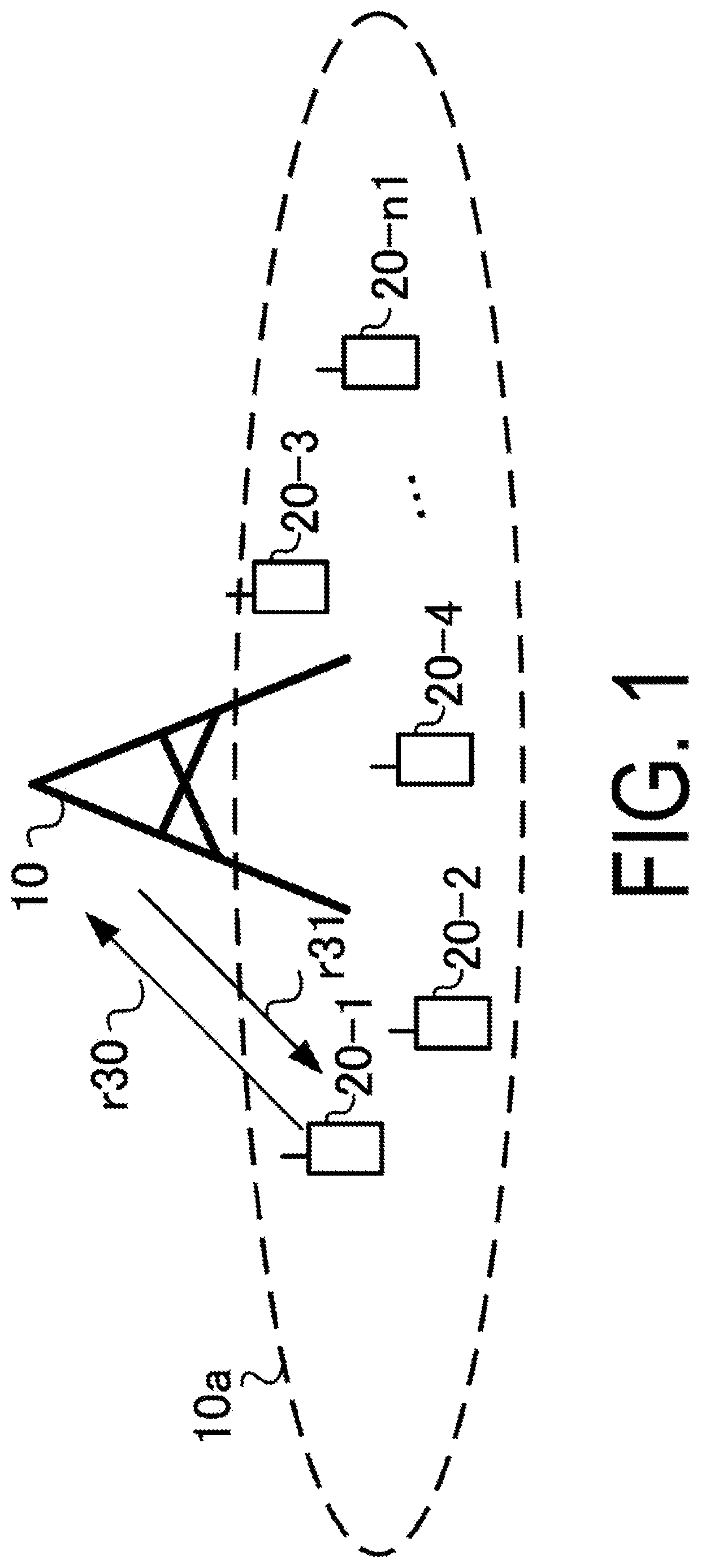
[0032]FIG. 1 is a diagram illustrating an example of a configuration of a communication system according to the present embodiment. The communication system according to the present embodiment includes a base station apparatus 10 and terminal apparatuses 20-1 to 20-n1 (n1 is a number of terminal apparatuses connected to the base station apparatus 10). The terminal apparatuses 20-1 and 20-n1 are also collectively referred to as terminal apparatuses 20. Coverage 10a is a range (a communication area) in which the base station apparatus 10 can connect to the terminal apparatus 20 (coverage 10a is also referred to as a cell).
[0033]In FIG. 1, radio communication of an uplink r30 includes at least the following uplink physical channels. The uplink physical channels are used for transmitting information output from a higher layer.[0034]Physical Uplink Control Channel (PUCCH)[0035]Physical Uplink Shared Channel (PUSCH)[0036]Physical Random Access Channel (PRACH)
[0037]The PUCCH is a physical ...
second embodiment
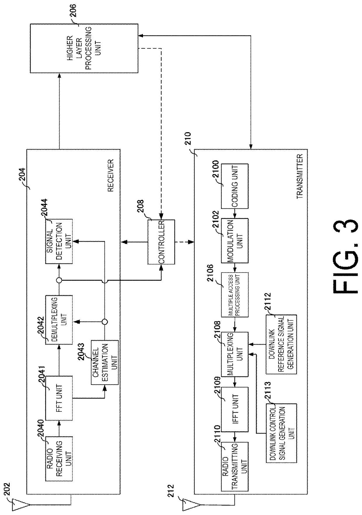
[0151]The present embodiment describes a method for determining a priority in a case that multiple uplink grants overlap in the time domain in a case that the SPS / grant free access Type 1 without activation using the DCI format is used, in order to achieve high reliability. A communication system according to the present embodiment includes the base station apparatus 10 and the terminal apparatus 20 illustrated in FIG. 3, FIG. 4, FIG. 5, and FIG. 6. Differences from / additions to the first embodiment will be mainly described below.
[0152]In the previous embodiment, the SPS / grant free access Type 2 is used, and the SPS-config is received through RRC signaling, and thereafter, activation is performed using the DCI format, thereby causing the configured uplink grant (periodic radio resource) to be available. On the other hand, in the SPS / grant free access Type 1 according to the present embodiment, in a case that rrcConfiguredUplinkGrant, besides the SPS-config, is received through RRC s...
third embodiment
[0168]The present embodiment describes a method for determining a priority in the case that multiple uplink grants destined to the C-RNTI overlap in the time domain. A communication system according to the present embodiment includes the base station apparatus 10 and the terminal apparatus 20 illustrated in FIG. 3, FIG. 4, FIG. 5, and FIG. 6. Differences from / additions to the first embodiment will be mainly described below.
[0169]The present embodiment describes a method for determining a priority of an uplink grant in a case that the uplink grant addressed to the C-RNTI in DCI format 0_0 / 0_1 overlaps in the time domain with the uplink grant addressed to the C-RNTI in DCI format 0_c.
[0170]FIG. 9 is a diagram illustrating an example of a notification of an uplink grant according to a third embodiment. The figure illustrates an example in which the uplink grant addressed to the C-RNTI is notified in DCI format 0_0 / 0_1 on the PDCCH in the slot x, and is allocated in the slots x+1 to x+3...
PUM
 Abstract
Description
Claims
Application Information
 - R&D
- Intellectual Property
- Life Sciences
- Materials
- Tech Scout
- Unparalleled Data Quality
- Higher Quality Content
- 60% Fewer Hallucinations
Browse by: Latest US Patents, China's latest patents, Technical Efficacy Thesaurus, Application Domain, Technology Topic, Popular Technical Reports.
© 2025 PatSnap. All rights reserved.Legal|Privacy policy|Modern Slavery Act Transparency Statement|Sitemap|About US| Contact US: help@patsnap.com


