Position estimation method for estimating position of interference signal source and position estimation system for performing the method

a position estimation and signal source technology, applied in multi-channel direction-finding systems using radio waves, receiveer monitoring, transmission monitoring, etc., can solve problems such as performance degradation, difficult to estimate the position of the interference signal source in an environment in which a plurality of reflected waves occurs due to the interference signal source, and widely used super-resolution schemes may not perform accurate position estimation

Active Publication Date: 2022-09-27
ELECTRONICS & TELECOMM RES INST
View PDF8 Cites 0 Cited by
  • Summary
  • Abstract
  • Description
  • Claims
  • Application Information

AI Technical Summary

Benefits of technology

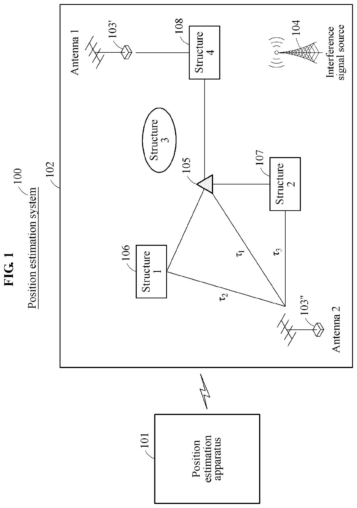
[0007]At least one example embodiment provides a position estimation method that may enhance an accuracy in estimating a position of an interference signal source using a virtual super-resolution scheme (including an algorithm) and a precise delay-space information analysis scheme in an indoor environment in which a multipath by a plurality of reflected waves is present, and a position estimation system for performing the method.
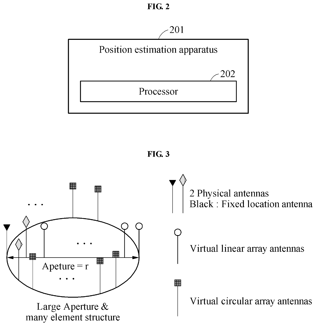
[0031]Also, according to some example embodiment, there is provided a method that may significantly enhance a position estimation accuracy in an indoor environment by acquiring azimuth information of primary received incident waves using a virtual array structure-based super-resolution scheme, by combining the acquired azimuth information and a delay-based space analysis model, and by determining a final position of an interference signal source.

Problems solved by technology

In an indoor environment, a communication system may have many factors that interfere with wireless communication due to interference by obstacles present indoors.
However, a method of using the fixed array antenna structure may be a method of using a fixed resolution, which makes it difficult to estimate the position of the interference signal source in an environment in which a plurality of reflected waves occurs due to the interference signal source.
Also, the widely used super-resolution scheme may not perform an accurate position estimation since it is difficult to estimate a number of reflected waves due to a high correlation.
However, the TDOA method may perform a position estimation to some extents if a bandwidth of an interference signal is wide and may not secure a time resolution if the bandwidth is small.
Thus, performance degradation may occur.
Thus, the above methods are generally used to assist the aforementioned position estimation systems and may not readily estimate the position of the interference signal source present indoors in reality.

Method used


Image

  • Position estimation method for estimating position of interference signal source and position estimation system for performing the method
  • Position estimation method for estimating position of interference signal source and position estimation system for performing the method
  • Position estimation method for estimating position of interference signal source and position estimation system for performing the method

Examples


Embodiment Construction

[0043]Hereinafter, some example embodiments will be described in detail with reference to the accompanying drawings. Regarding the reference numerals assigned to the elements in the drawings, it should be noted that the same elements will be designated by the same reference numerals, wherever possible, even though they are shown in different drawings. Also, in the description of embodiments, detailed description of well-known related structures or functions will be omitted when it is deemed that such description will cause ambiguous interpretation of the present disclosure.

[0044]The following detailed structural or functional description of example embodiments is provided as an example only and various alterations and modifications may be made to the example embodiments. Accordingly, the example embodiments are not construed as being limited to the disclosure and should be understood to include all changes, equivalents, and replacements within the technical scope of the disclosure.

[...


PUM


Abstract

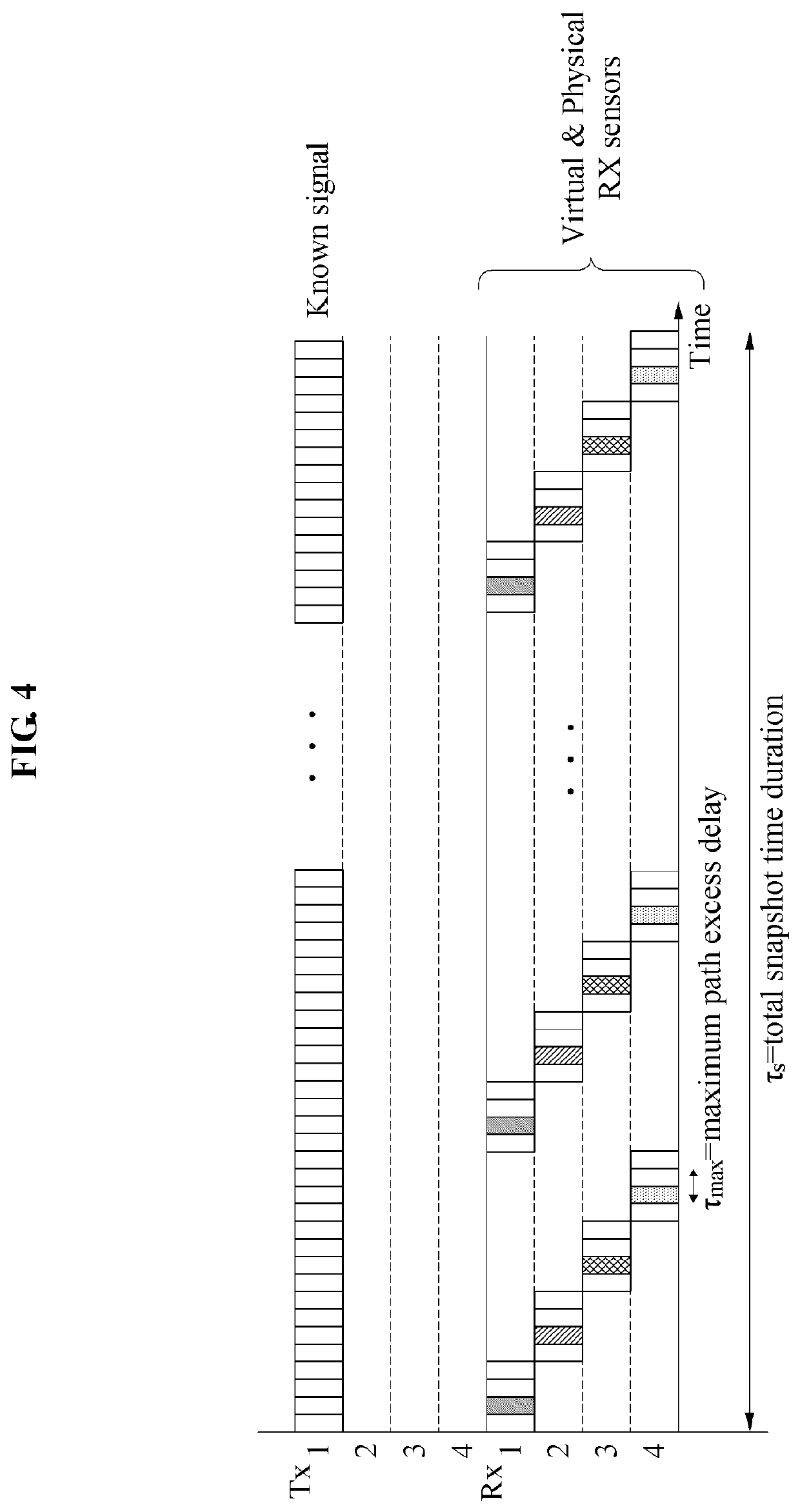
Disclosed is a position estimation method for estimating a position of an interference signal source and a position estimation system for performing the method. The position estimation method may implement an indoor delay-space analysis structure by transmitting and receiving a known signal and a virtual array structure-based direction finding algorithm in an indoor environment in which a plurality of reflected waves is present and may increase an estimation probability for the position of the interference signal source.

Description

CROSS-REFERENCE TO RELATED APPLICATION(S)[0001]This application claims the priority benefit of Korean Patent Application No. 10-2018-0062828 filed on May 31, 2018, and Korean Patent Application No. 10-2018-0133657 filed on Nov. 2, 2018 in the Korean Intellectual Property Office, the disclosures of which are incorporated herein by reference for all purposes.BACKGROUND1. Field[0002]One or more example embodiments relate to a position estimation system and a position estimation method for estimating a position of an interference signal source, and more particularly, to a technique for estimating a position of an interference signal source in an indoor environment in which a plurality of reflected waves is present.2. Description of Related Art[0003]In an indoor environment, a communication system may have many factors that interfere with wireless communication due to interference by obstacles present indoors. The communication system may estimate a position of an interference signal sou...

Claims


Application Information

Patent Timeline
Patent Type & Authority Patents(United States)
IPC IPC(8): H04B15/00H04B17/27H04B17/336G01S13/46
CPCH04B17/27G01S13/46H04B17/336G01S3/74H04B17/345G01S5/0252G01S5/0221
Inventor KIM, CHUNG SUPKIM, HYUK JECHONG, YOUNG JUNLIM, JONG SOOHONG, JU YEON
Owner ELECTRONICS & TELECOMM RES INST
Why Eureka
Try Eureka