Quality determination device and quality determination method
a quality determination and quality technology, applied in the direction of computer control, program control, instruments, etc., can solve the problems of requiring a large amount of time and man-hours for such work, and achieve the effect of determining quality easily and efficiently
- Summary
- Abstract
- Description
- Claims
- Application Information
AI Technical Summary
Benefits of technology
Problems solved by technology
Method used
Image
Examples
embodiment
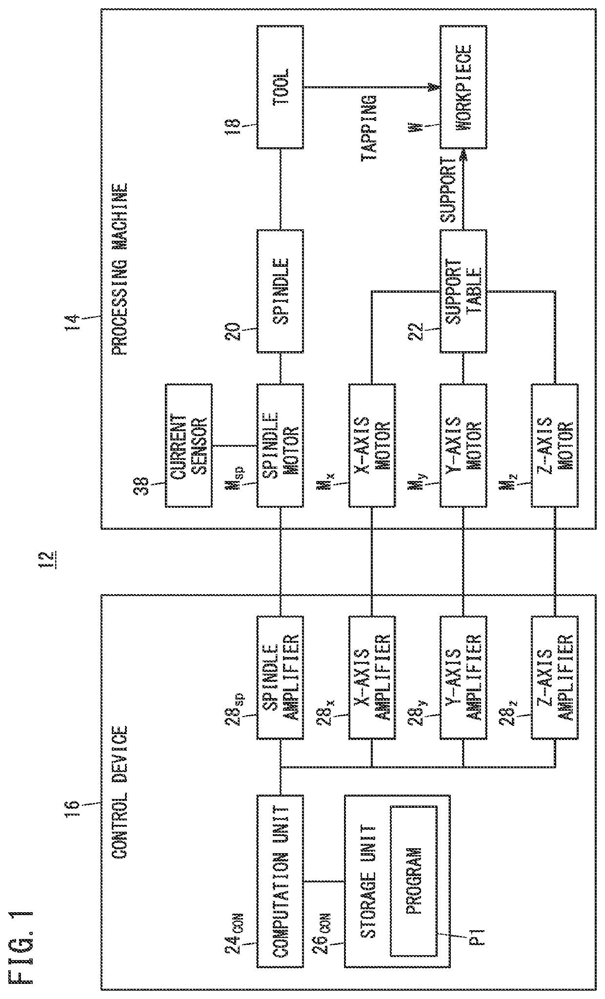
[0020]FIG. 1 is a schematic configuration diagram showing a configurational example of a machine tool 12 for tapping.
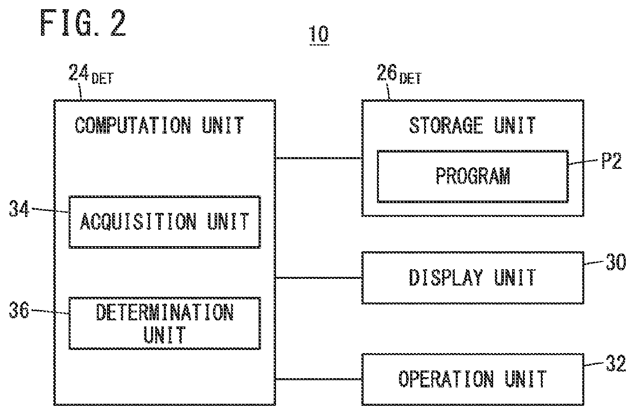
[0021]Before explaining a quality determination device 10 of the present embodiment, a configurational example of the machine tool 12 for forming screw holes to be subject to the quality (acceptance / rejection) determination by the quality determination device 10 will be described with reference to FIG. 1.
[0022]The machine tool 12 performs tapping on a workpiece W, and includes a processing machine 14 and a control device 16. Of these, the processing machine 14 includes a spindle 20 to which a tool 18 also called a tap is attached, and a spindle motor Msp connected to the spindle 20. Further, the processing machine 14 further includes a support table 22 for supporting the workpiece W to be tapped, and an X-axis motor Mx, a Y-axis motor My, and a Z-axis motor Mz connected to the support table 22.
[0023]Of these, the spindle motor Msp is a spindle motor that rotates the t...
modification 1
(Modification 1)
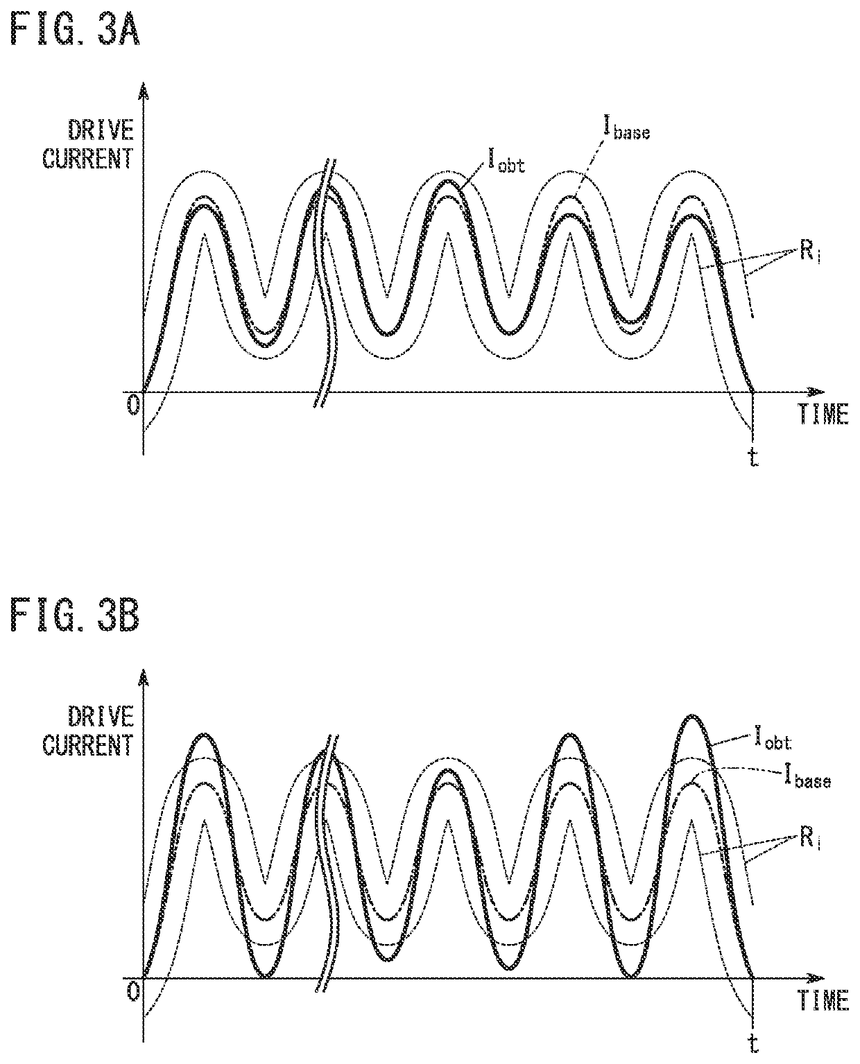
[0062]The determination unit 36 of the embodiment determines acceptance or rejection of the screw hole, based on whether or not the drive current falls within a predetermined range. The mode of determination that the determination unit 36 can adopt is not limited to this.
[0063]For example, the quality determination device 10 may calculate the electric power or torque of the motor M during tapping, from the drive current of the motor M during the tapping. Further, the quality (acceptance or rejection) of the screw hole formed by the tapping may be determined based on whether or not the electric power or torque of the motor M during the tapping falls within a predetermined range.
[0064]In relation to the above, a configuration of the quality determination device 10 of this modification will be described. However, in the following, the description of the items already explained in the above embodiment will be omitted as appropriate.
[0065]FIG. 5 is a schematic configurati...
modification 2
(Modification 2)
[0070]In the above, cases have been described that acceptance or rejection of a screw hole can be determined based on whether or not or not the drive current, the electric power, or the torque of the motor M that is being tapped falls within a predetermined range. Modes of determination that the determination unit 36 can adopt are not limited to these.
[0071]For example, the quality determination device 10 may determine the quality (acceptance or rejection) of the screw hole, based on whether or not the frequency of the drive current, the electric power, or the torque falls within a previously defined frequency range (hereinafter, also referred to as “predetermined frequency range”).
[0072]In relation to this, a configuration of a quality determination device 10 of this modification will be described. However, in the following, the explanation of the items already explained so far will be omitted as appropriate.
[0073]FIG. 6 is a schematic configuration diagram of a qua...
PUM
| Property | Measurement | Unit |
|---|---|---|
| drive current | aaaaa | aaaaa |
| electric power | aaaaa | aaaaa |
| torque | aaaaa | aaaaa |
Abstract
Description
Claims
Application Information
 - R&D
- Intellectual Property
- Life Sciences
- Materials
- Tech Scout
- Unparalleled Data Quality
- Higher Quality Content
- 60% Fewer Hallucinations
Browse by: Latest US Patents, China's latest patents, Technical Efficacy Thesaurus, Application Domain, Technology Topic, Popular Technical Reports.
© 2025 PatSnap. All rights reserved.Legal|Privacy policy|Modern Slavery Act Transparency Statement|Sitemap|About US| Contact US: help@patsnap.com


