Method and device for measuring dimension of constant velocity joint

a technology of constant velocity universal joints and measurement methods, applied in the direction of mechanical measuring arrangements, couplings, instruments, etc., can solve the problems of complex operations and efficient measurements, and achieve the effect of reducing the time required to measure a dimension, improving measurement efficiency, and easy determining an offs

Inactive Publication Date: 2008-07-01
HONDA MOTOR CO LTD
View PDF17 Cites 1 Cited by
  • Summary
  • Abstract
  • Description
  • Claims
  • Application Information

AI Technical Summary

Benefits of technology

[0018]It is a general object of the present invention to provide a method of measuring a dimension of a constant velocity universal joint to easily and efficiently determine an offset of an outer member or an inner member.
[0058]Either one of the dimension measuring apparatus is capable of easily determining an offset according to a single simple dimension measuring process. Therefore, the time required to measure a dimension can be reduced, and the measuring efficiency can be increased.

Problems solved by technology

Performing such operations is a complex task and does not lead to efficient measurements.

Method used


Image

  • Method and device for measuring dimension of constant velocity joint
  • Method and device for measuring dimension of constant velocity joint
  • Method and device for measuring dimension of constant velocity joint

Examples


first embodiment

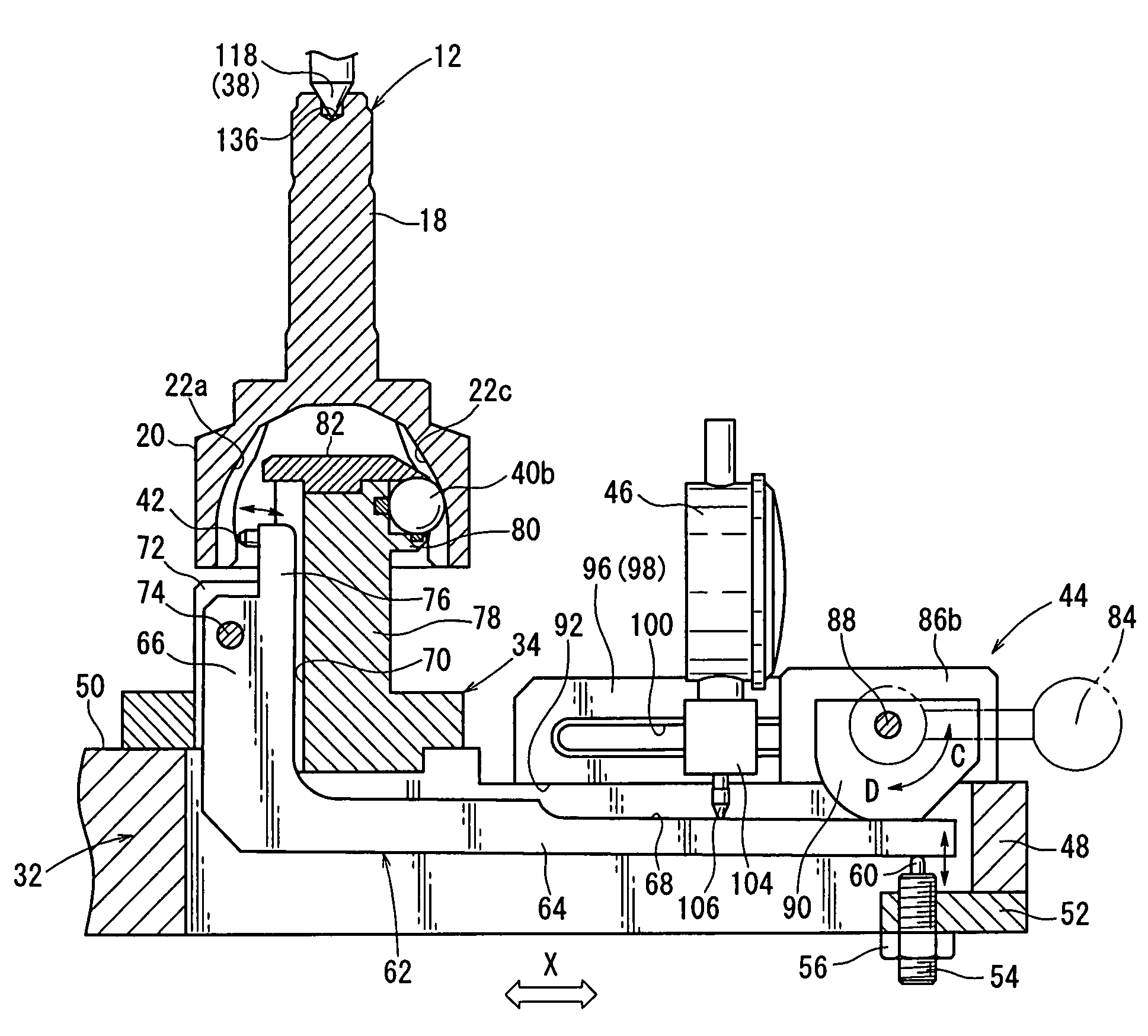
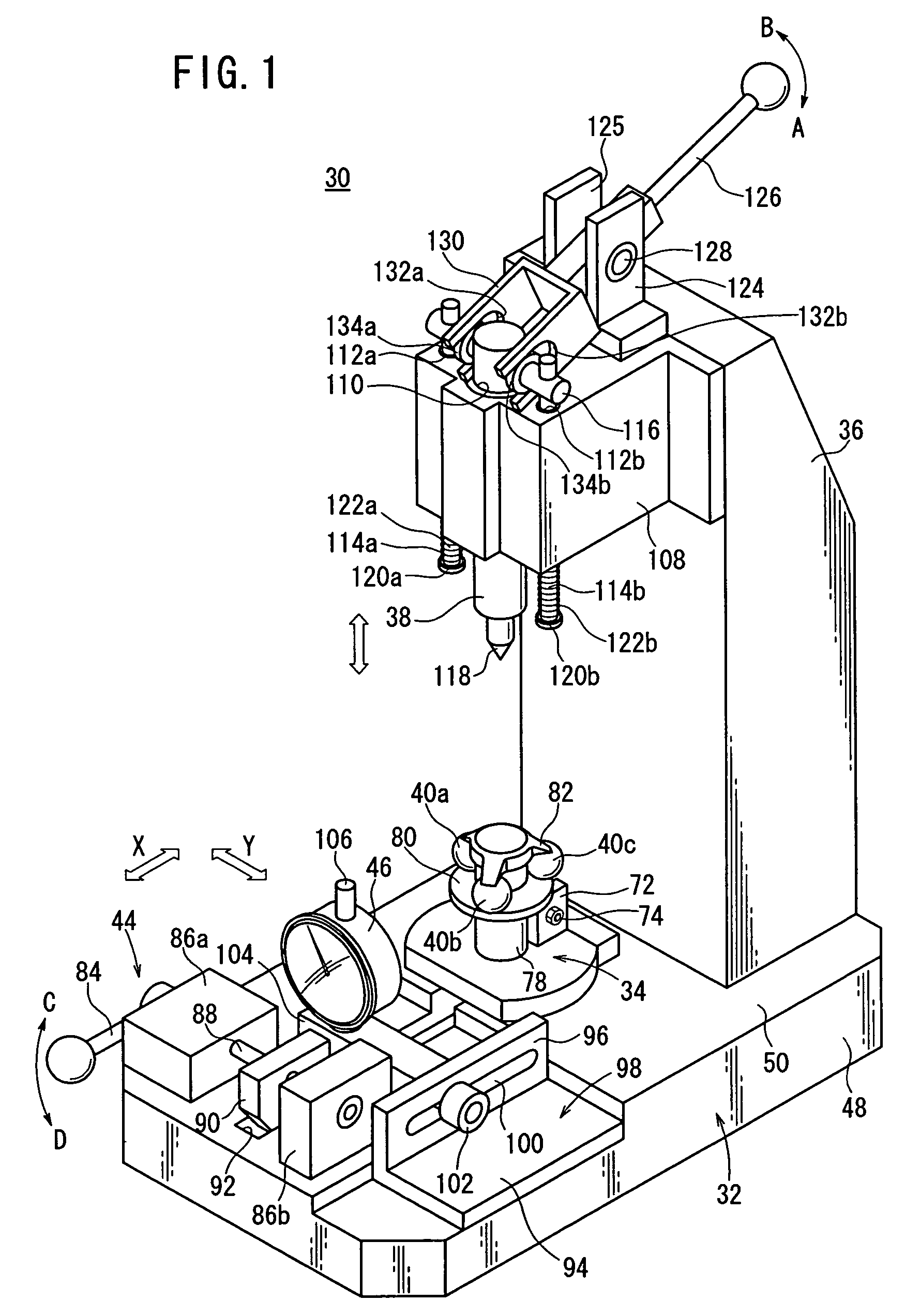
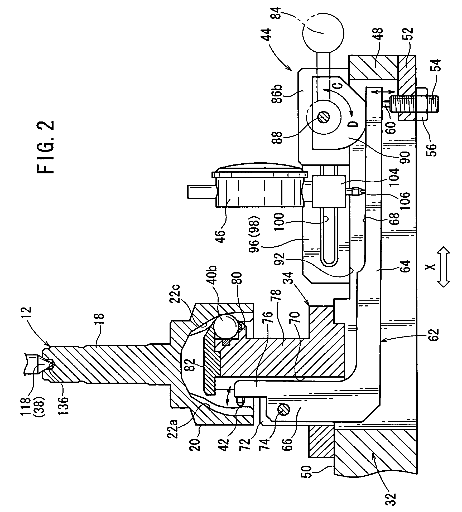
[0069]FIG. 1 shows in schematic perspective an apparatus for measuring a dimension of a constant velocity universal joint (hereinafter referred to as “outer member dimension measuring apparatus”) according to the present invention, and FIG. 2 shows the apparatus in fragmentary vertical cross section. The outer member dimension measuring apparatus 30 has a base 32, a support 34 which is vertically disposed on the base 32, a holder rod 38 disposed as a holder above the support 34 by a post 36, three balls 40a through 40c positioned on and fixed to a distal end of the support 34, a measuring probe 42 (see FIG. 2) disposed between the balls 40a, 40c, a displacing mechanism 44 for turning the measuring probe 42, and a microgage 46 serving as a displacement indicator for indicating an amount of displacement of the measuring probe 42.

[0070]As shown in FIG. 2, the base 32 comprises a hollow body having a side plate 48 and a top plate 50. A projecting plate 52 extending toward the center of ...

second embodiment

[0103]the present invention will be described below.

[0104]FIG. 5 shows in schematic perspective an apparatus for measuring a dimension of a constant velocity universal joint (hereinafter referred to as “inner member dimension measuring apparatus”) according to a second embodiment of the present invention, and FIG. 6 shows the apparatus in fragmentary vertical cross section. The inner member dimension measuring apparatus 230 has a mount 232, a housing 236 placed on a top plate 234 of the mount 232, a holder mechanism 242 having a holder rod 240 disposed above the housing 236 by a post 238, three balls 244a through 244c fixedly positioned in the housing 236, a measuring probe 246 (see FIG. 6) disposed between the balls 244a, 244c, a displacing mechanism 248 for turning the measuring probe 246, and a microgage 250 serving as a displacement indicator for indicating an amount of displacement of the measuring probe 246.

[0105]As shown in FIG. 5, the mount 232 has a bottom plate 252, a top ...


PUM


Abstract

A method and a device for measuring the dimensions of a constant velocity joint. In the method, for example, the cylindrical part of an outer member with a specified offset value is supported on the support part of a dimension measuring device for the outer member. On the other hand, a holding bar is inserted into a recessed part formed in the shaft part of the outer member. In this case, balls installed at the tip of the support part are inserted into the ball grooves of the cylindrical part. In this state, a rotating member is rotated to bring a probe into contact with the inside wall of the cylindrical part. The measurement core of a micro gauge is displaced according to the displacement of the probe, and the amount of the displacement thereof is displayed as the amount of the variation of the needle of the micro gauge.

Description

TECHNICAL FIELD[0001]The present invention relates to a method of and an apparatus for measuring a dimension of a constant velocity universal joint, i.e., the distance (offset) from the center of a spherical inner surface of an outer member and an inner member of the constant velocity universal joint to the center of ball grooves thereof.BACKGROUND ART[0002]FIG. 8 is a schematic cross-sectional view of a Barfield-type constant velocity universal joint (hereinafter referred to as “constant velocity universal joint”) 10 which has heretofore been known. The constant velocity universal joint 10 has an outer member 12, an inner member 14, and rolling balls 16 interposed between the outer member 12 and the inner member 14.[0003]The outer member 12 has a shank 18 and an open tubular member 20. The tubular member 20 has six angularly equally spaced ball grooves 22a through 22f defined in a curved inner wall surface thereof.[0004]The inner member 14 is held by a retainer 24 and inserted in t...

Claims


Application Information

Patent Timeline
Patent Type & Authority Patents(United States)
IPC IPC(8): G01B5/14
CPCF16D3/223G01B5/02F16D3/2245F16D2250/00
Inventor TAKAGI, TAKESHIKOYAMA, MINORUNAKATANI, MITSUYOSHI
Owner HONDA MOTOR CO LTD
Why Eureka
Try Eureka