Blind mate thermal cooling solution for small form factor pluggable transceiver

a plug-in transceiver and thermal cooling technology, applied in the cage field, can solve the problems of poor heat rejection of fins within a standard module form factor, poor thermal conduction path between heatsinks and modules, and current cooling solutions that cannot permit doubled power consumption

Active Publication Date: 2022-10-04
GOOGLE LLC
View PDF27 Cites 2 Cited by
  • Summary
  • Abstract
  • Description
  • Claims
  • Application Information

AI Technical Summary

Problems solved by technology

Current cooling solutions may not be able to permit a doubled power consumption while maintaining the same exterior form factor.
One conventional cooling solution provides a heatsink built onto the module using fins, but such fins may experience poor heat rejection within a standard module form factor.
Another conventional cooling solution provides a heatsink built onto the cage into which the module is inserted, but such a solution may result in a poor thermal conduction path between the heatsink and the module due to minimal contact pressure between the heatsink and the module, caused by tolerances in the distance between the heatsink and the confronting surface of the module.
Therefore, conventional cooling solutions may not effectively manage the thermal load of the next generation of some modules while maintaining the same standard exterior form factor, which may result in damage to the module and / or the circuit board, or which may require an undesirable modification of the standard exterior form factor.

Method used


Image

  • Blind mate thermal cooling solution for small form factor pluggable transceiver
  • Blind mate thermal cooling solution for small form factor pluggable transceiver
  • Blind mate thermal cooling solution for small form factor pluggable transceiver

Examples


Embodiment Construction

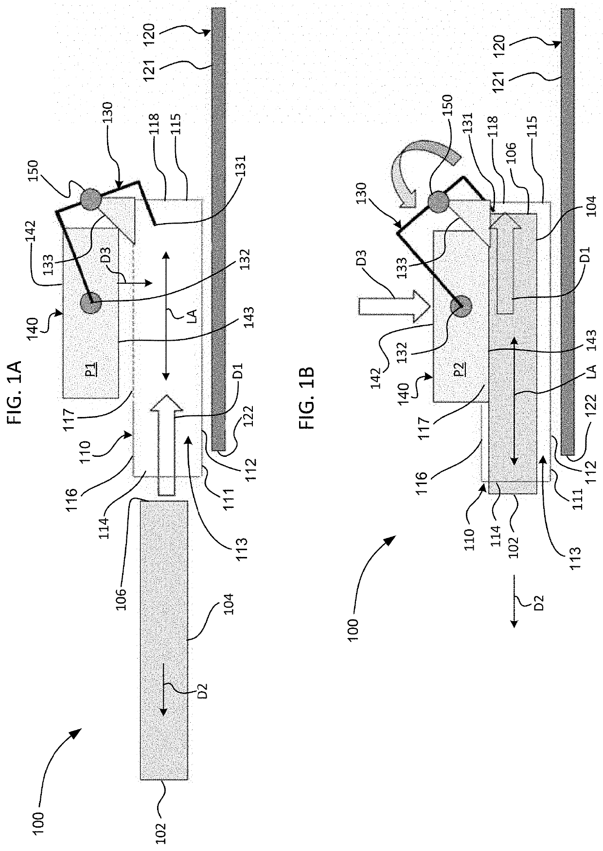
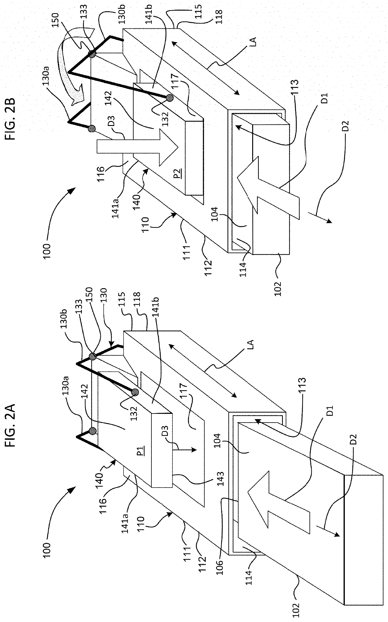
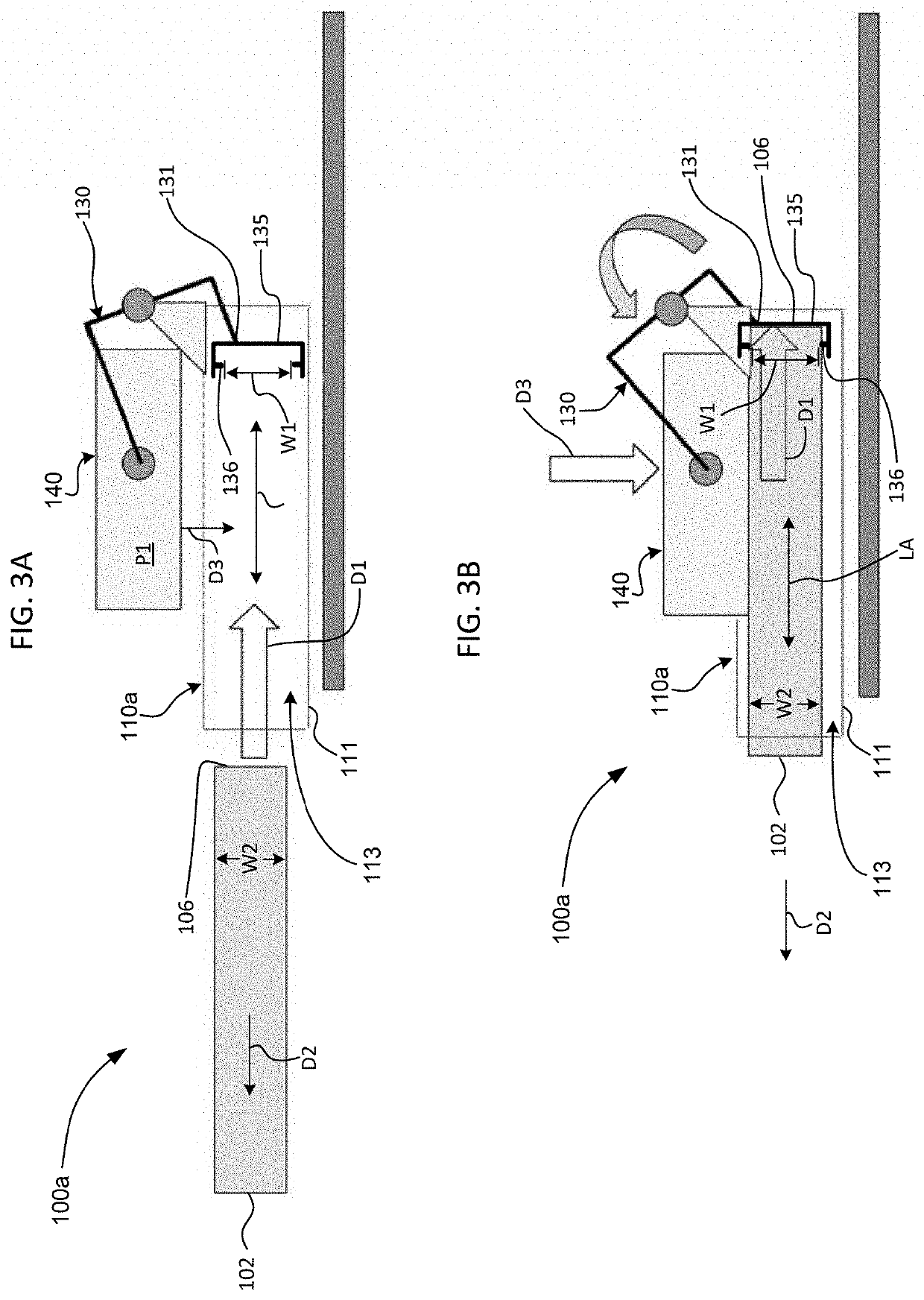
[0018]The technology relates generally to a cage configured to removably receive a module, such as a small form factor high power pluggable transceiver, and a method for removably inserting such a module into a cage. For example, and as illustrated in FIGS. 1A through 2B, a system 100 may include a cage 110 and a circuit panel 120. A frame 111 of the cage 110 may be fixedly mounted to a major surface 121 of the circuit panel 120 at a peripheral edge 122 thereof. The cage 110 may be configured to removably receive a module 102 therein.

[0019]The module 102 may be a small form factor high power pluggable transceiver, which may be an optical module that has a high thermal load compared to conventional optical modules. The power consumption of such an optical module may require almost double the power consumption of a conventional optical module while maintaining the same exterior form factor.

[0020]The frame 111 of the cage 110 may include a plurality of panels 112 joined to one another,...


PUM


Abstract

The technology relates to a cage configured to removably receive a module. The cage may include a frame comprising a plurality of panels joined to one another, a lever pivotably coupled to the frame, and a heatsink pivotably coupled to the lever. The panels together may extend around a longitudinal recess configured to receive the module therein. The longitudinal recess may define a longitudinal axis thereof. A first one of the panels may have an aperture defined therein in communication with the longitudinal recess. A first end of the lever may extend into the longitudinal recess. The heatsink may be pivotably coupled to a second end of the lever opposite the first end. The heatsink may be movable in a translation direction transverse to the longitudinal axis. The heatsink may be translatable between a first position outside of the longitudinal recess and a second position partially inside the longitudinal recess.

Description

BACKGROUND[0001]Optical module bandwidths have substantially increased due to machine learning demands, which has increased the importance of managing the thermal load of such modules. The next generation of some modules may require the power consumption to be almost doubled while maintaining the same standard exterior form factor. Current cooling solutions may not be able to permit a doubled power consumption while maintaining the same exterior form factor.[0002]One conventional cooling solution provides a heatsink built onto the module using fins, but such fins may experience poor heat rejection within a standard module form factor. Another conventional cooling solution provides a heatsink built onto the cage into which the module is inserted, but such a solution may result in a poor thermal conduction path between the heatsink and the module due to minimal contact pressure between the heatsink and the module, caused by tolerances in the distance between the heatsink and the confr...

Claims


Application Information

Patent Timeline
Patent Type & Authority Patents(United States)
IPC IPC(8): H05K7/20H01R13/502G02B6/42H01R43/26
CPCH01R13/502G02B6/42G02B6/4269H01R43/26H05K7/20G02B6/4261H01L23/4093H05K7/2049
Inventor CHIU, JERRYBEAUCHEMIN, MELANIE
Owner GOOGLE LLC
Why Eureka
Try Eureka