Quick-connect thermal solution for computer hardware testing

a technology of thermal solution and computer hardware, applied in the direction of cooling/ventilation/heating modification, semiconductor device details, semiconductor/solid-state device details, etc., can solve the problems of customer's thermal solution performing better than a manufacturer's thermal solution, the labor cost involved in installing and removing thermal solutions has become significant, and the thermal solution of the customer may not perform well. , to achieve the effect of quick and easy removal

Active Publication Date: 2006-10-24
NVIDIA CORP
View PDF10 Cites 15 Cited by
  • Summary
  • Abstract
  • Description
  • Claims
  • Application Information

AI Technical Summary

Benefits of technology

[0010]One advantage of the disclosed quick-connect system is that it can be connected to a graphics card in a few simple steps. Among other things, this capability enables the cooling module to be thermally coupled to the GPU temporarily during performance testing. Once testing is completed, the quick-connect system can be quickly and easily removed from the graphics card, thereby allowing the graphics card to be shipped to the customer without an attached thermal solution.

Problems solved by technology

As thermal solution assemblies have become more complex, the labor cost involved in installing and removing thermal solutions has become significant.
A significant drawback of this approach is that customers oftentimes want to use their own thermal solutions with the graphics cards, not the manufacturers' thermal solutions.
Second, a customer's thermal solution may perform better than a manufacturer's thermal solution.
Under the current approach, however, if a customer wants to use its own thermal solution, then that customer must incur the additional costs associated with removing the manufacturer's thermal solution from the graphics card and installing its own thermal solution.

Method used


Image

  • Quick-connect thermal solution for computer hardware testing
  • Quick-connect thermal solution for computer hardware testing
  • Quick-connect thermal solution for computer hardware testing

Examples


Embodiment Construction

)

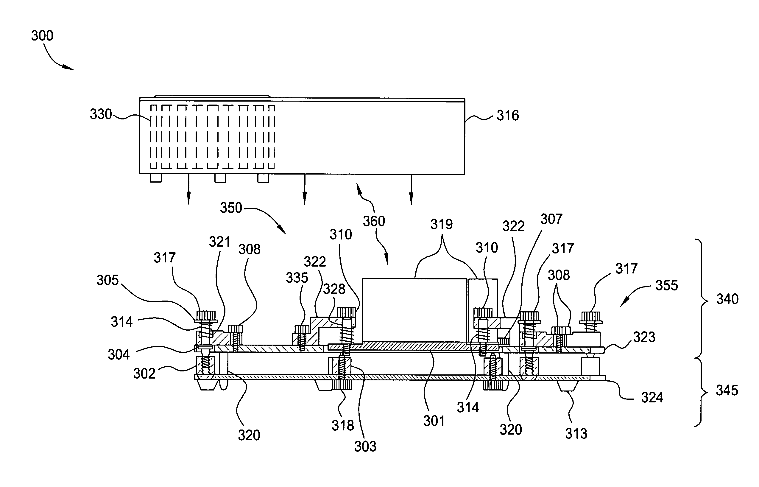
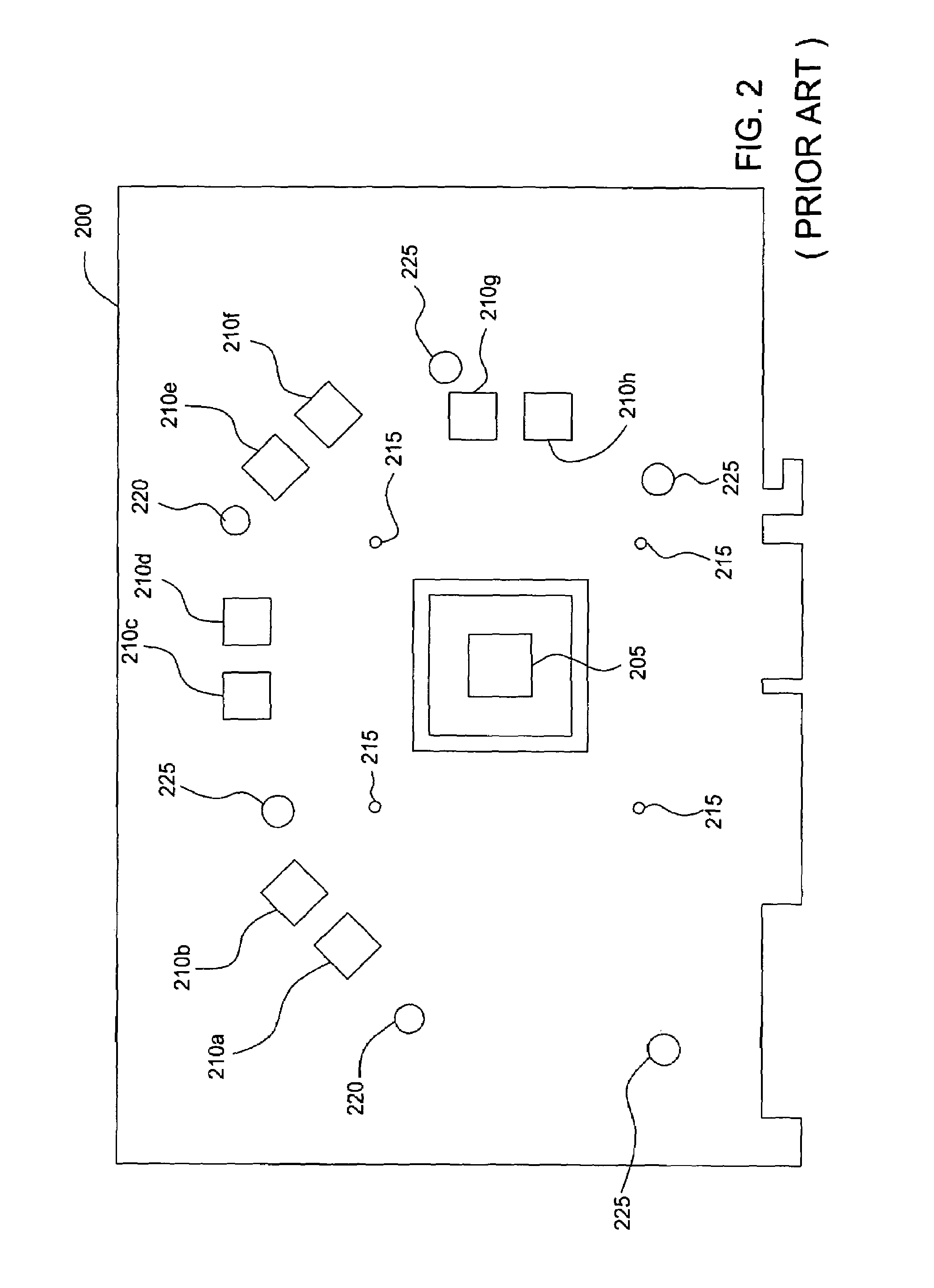
[0017]FIGS. 3A–D are various views of a quick-connect thermal solution 300, according to one embodiment of the present invention. As shown the quick-connect thermal solution 300 is configured to be thermally and structurally coupled to a graphics card, such as the graphics card 200 illustrated in FIG. 2. In alternate embodiments, the quick-connect thermal solution 300 may be configured to be coupled to any type of circuit board for cooling a heat-generating electronic device mounted on that circuit board.

[0018]For ease of illustration, the graphics card 200 is not illustrated these figures. If shown in FIG. 3A, for example, the graphics card 200 would be located between the outer plate 323 and a bottom plate 324, the top side of the graphics card 200 including the GPU 205 and the memory units 210a–h being disposed adjacent to outer plate 323. All references to directions, such as “top” and “bottom”, are for reference purposes only and in no way limit the scope of the present invent...


PUM


Abstract

The present invention represents a significant advancement in the field of thermal solutions for computer hardware. In one embodiment, a quick-connect system for cooling a heat-generating electronic device is provided. The electronic device is mounted to a first side of a circuit board. The system includes a first plate having an opening and configured to be coupled to the first side of the circuit board. The system further includes a second plate disposed within the opening and coupled to the first plate with a first suspension system, wherein the first suspension system is configured to enable the second plate to be disposed substantially flat against the electronic device when the first plate is coupled to the first side of the circuit board. The system further includes a cooling module thermally coupled to the second plate and configured to dissipate heat transferred from the electronic device to the second plate.

Description

BACKGROUND OF THE INVENTION[0001]1. Field of the Invention[0002]This invention relates generally to computer hardware and more particularly to a quick-connect thermal solution for testing computer hardware.[0003]2. Description of the Related Art[0004]FIG. 1 is an isometric view illustrating a prior art thermal solution assembly 100 used, for example, to cool heat-generating electronic devices in a computer system, such as a graphics processor. As shown, thermal solution assembly 100 characteristically includes a fan 106, fins 109 and a bottom plate 111. Typically, thermal solution 100 is thermally coupled to the graphics processor, for example using thermal adhesive or grease having thermal properties that facilitate transferring heat generated by the electronic device to the bottom plate 111. Thermal solution assembly 100 may also include a heat sink lid (not shown), which, among other things, prevents particles and other contaminants from entering fan 106 and air blown from fan 10...

Claims


Application Information

Patent Timeline
Patent Type & Authority Patents(United States)
IPC IPC(8): H05K7/20
CPCH01L23/4006H01L23/467H01L2023/405H01L2023/4062H01L2023/4087H01L2924/0002H01L2924/00
Inventor SORENSEN, GEORGE A.MICHAUD, BRUCE R.
Owner NVIDIA CORP
Why Eureka
Try Eureka