

Flexible lighiing device and display panel using micro LED chips
a technology of flexible lighting and led chips, which is applied in the direction of semiconductor devices for light sources, lighting and heating apparatus, basic electric elements, etc., can solve the problems of low luminous efficiency, limit the flexibility of conventional surface lighting devices to planar shapes, and conventional surface lighting devices are not adapted to the surface shapes of various objects. , to achieve the effect of ensuring the flexibility of flexible substrates, small thicknesses, and efficient and economically feasibl
Active Publication Date: 2022-10-25
LUMENS
View PDF10 Cites 0 Cited by
- Summary
- Abstract
- Description
- Claims
- Application Information
AI Technical Summary
Benefits of technology
The solution enables flexible LED lighting devices that can be curved and maintain uniform light emission, fabricated over large areas, and effectively removes air gaps in micro-LED display panels, suitable for various applications including design and indoor lighting.
Problems solved by technology
However, the rigidity of printed circuit boards mounted with LED packages limit conventional surface lighting devices to planar shapes.
Thus, conventional surface lighting devices are not adapted to the surface shapes of various objects and are always installed only on the surface of planar objects.
However, the problems of OLEDs, such as high price and low luminous efficiency, make it difficult to commercialize flexible surface lighting devices using OLEDs.
However, several technical limitations (for example, limited areas of circuit boards where general die bonders can be used and limited sizes where single flexible circuit boards are applicable) make it difficult to fabricate large-area flexible LED lighting devices.
However, air may remain in the gap lines, causing defects in the micro-LED display panel.
Lines are formed between the light-transmitting film pieces and there is a great difference in refractive index between the lines and the light-transmitting film pieces, resulting in light leakage.
Method used
View moreImage
Smart ImageViewing Examples

Examples
first embodiment
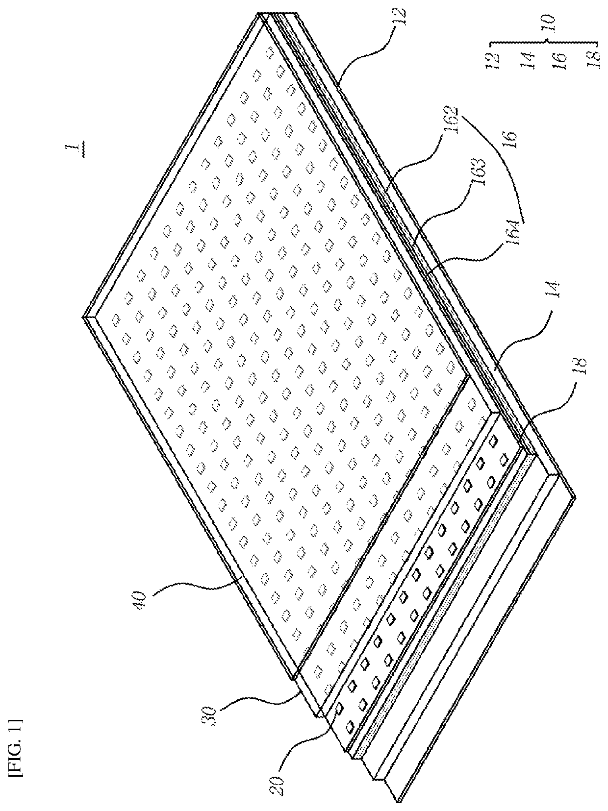
[0022]FIG. 1 is a partially cut-away perspective view illustrating a flexible surface lighting device according to a first disclosure.
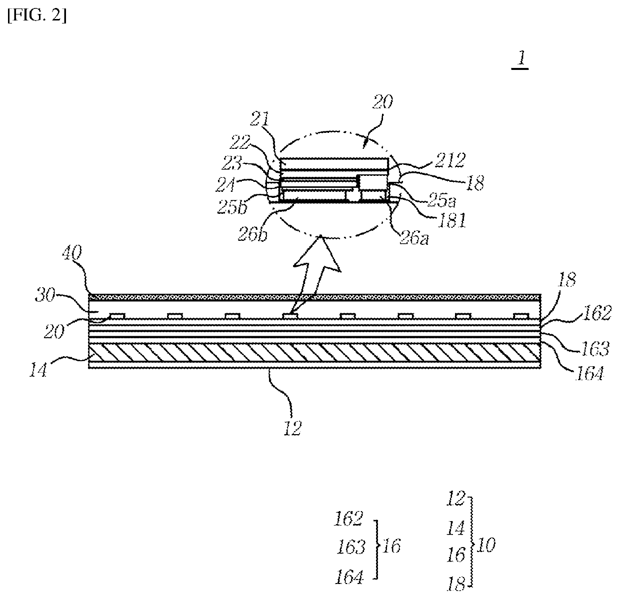
[0023]FIG. 2 is a cross-sectional view illustrating the flexible surface lighting device according to the first embodiment of the first disclosure.
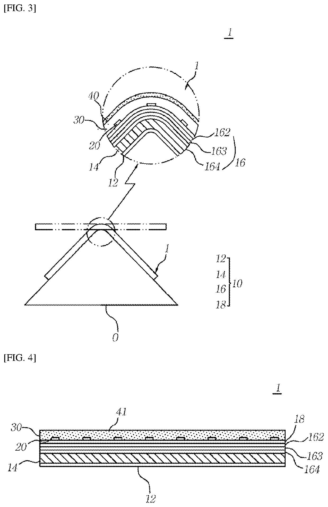
[0024]FIG. 3 illustrates an application example of the flexible surface lighting device of FIGS. 1 and 2.
second embodiment
[0025]FIG. 4 is a cross-sectional view illustrating a flexible surface lighting device according to the first disclosure.
third embodiment
[0026]FIG. 5 is a cross-sectional view illustrating a flexible surface lighting device according to the first disclosure.
Login to View More PUM
| Property | Measurement | Unit |
|---|---|---|
| length | aaaaa | aaaaa |
| length | aaaaa | aaaaa |
| thickness | aaaaa | aaaaa |
Abstract
A flexible surface lighting device is disclosed. The flexible surface lighting device includes: a flexible substrate including an upper insulating film, a lower insulating film, and a thin metal layer interposed between the upper and lower insulating films; a plurality of micro-LED chips two-dimensionally arrayed on the top surface of the flexible substrate; and a flexible light-transmitting resin part disposed on the top surface of the flexible substrate to cover the top and side surfaces of the micro-LED chips. The flexible substrate includes a white reflective layer in contact with the light-transmitting resin part on the upper insulating film.
Description
TECHNICAL FIELD[0001]The present invention relates to a flexible lighting device and a display panel using micro-LED chips.BACKGROUND ART[0002]This section provides background information related to the present invention which is not necessarily prior art.[0003]Surface lighting devices use a plurality of LED packages as light sources are known. Such surface lighting devices are classified into direct-type and edge-type surface lighting devices depending on the arrangement of LED packages. Direct-type surface lighting devices include a plurality of LED packages arranged two-dimensionally over a large area directly under a light-diffusing plate, whereas edge-type surface lighting devices include LED packages arranged along the edges of a rigid light guide plate. However, the rigidity of printed circuit boards mounted with LED packages limit conventional surface lighting devices to planar shapes. Thus, conventional surface lighting devices are not adapted to the surface shapes of vario...
Claims
Login to View More Application Information
Patent Timeline
 Patent Type & AuthorityPatents(United States)
IPC IPC(8): H01L27/15H01L23/538H01L25/13H01L33/58H01L33/60H01L33/62H01L33/64H01L33/52H01L33/44
CPCH01L27/156H01L23/5387H01L25/13H01L33/44H01L33/52H01L33/58H01L33/60H01L33/62H01L33/642H01L2933/0058H01L2933/0066H01L2933/0075F21K9/60F21S2/00F21V23/00H01L33/54H01L25/0753H01L2933/0091H01L33/50H01L33/486
InventorLEE, JEONGWOOLIM, JUNHYUNGHONG, HYUNPYOCHANG, JIHYEKIM, BOGYUNRO, YOUNGKYOKIM, GUNHAMUN, JUGYEONG
OwnerLUMENS