Inverted brushless conveyor belt cleaner system

Active Publication Date: 2022-11-01
CROSSFORD INT
View PDF32 Cites 0 Cited by
  • Summary
  • Abstract
  • Description
  • Claims
  • Application Information

AI Technical Summary

Benefits of technology

This patent describes a conveyor belt cleaner system that allows for cleaning to occur on the return path of the conveyor belt, rather than the forward path. The system includes mounting plates, a backing platen, and a bottom tray with a cleaning subassembly. The cleaning subassembly has a steam chamber and a vacuum chamber with wipers for each section of the conveyor belt. The system also has an adjustable steam header for varying the width of steam application based on the width of the conveyor belt, and the wipers are mounted on springs to ensure continuous wiping of the conveyor belt surface. The technical effect of this invention is the ability to clean the conveyor belt at a specific position on its return path rather than the forward path, which can improve efficiency and prevent wear on the wipers.

Problems solved by technology

In the prior art, conveyor belts used in various commercial activities are known to become soiled, typically with spillage from materials being conveyed or treated on the belt.
A further shortcoming is that the required pair of transverse guides adds an undesirable level of complexity to the structure of the frame.
A shortcoming of this system is that a transversely reciprocating cleaning system cannot clean equally all areas of a moving substrate unless the speed of reciprocation is much greater than the speed of the substrate past the system.
However, a common problem arises when applying a system designed for a first belt width to cleaning of a belt having a second and narrower width wherein the steam application occurs on both the belt surface and on the fixed conveyor frame and belt backing elements outboard of the moving belt.
Such steam overspray results in undesirable condensation and water pooling on conveyor frame surfaces outboard of the belt, which eventually requires corrective measures which may include stopping the conveyor and the cleaning process to mop up the excess water.

Method used


Image

  • Inverted brushless conveyor belt cleaner system
  • Inverted brushless conveyor belt cleaner system
  • Inverted brushless conveyor belt cleaner system

Examples


Embodiment Construction

[0031]Throughout the following description, specific elements are set forth to provide a more thorough understanding of the invention. However, in some embodiments the invention may be practiced without some of these elements. In other instances, well known elements have not been shown or described in detail to avoid unnecessarily obscuring the disclosure. Accordingly, the specification and drawings are to be regarded as illustrative rather than restrictive. It is to be further noted that the drawings may not be to scale.

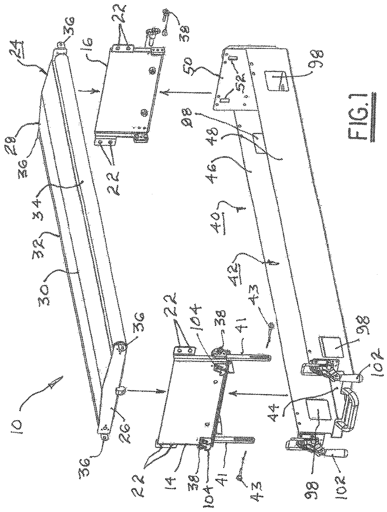
[0032]Referring now to FIGS. 1 through 10, a supportive subassembly 10 (FIG. 1) for an inverted brushless conveyor cleaner system 12 (FIG. 10) comprises first and second end plates 14,16 suitable for attachment to opposite sides of a frame 18 of a conveyor belt system 20 in the return path 21 thereof (FIG. 4) via bolt holes 22. A backing platen subassembly 24 comprises a first and second end pieces 26,28 supporting a backing platen 30 and first and second rollers 32...


PUM


Abstract

A conveyor belt cleaner system comprising a platen subassembly positioned transversely of the return path of the conveyor belt; a steam chamber disposed adjacent a first portion of the conveyor belt, the steam chamber including a steam header; a vacuum chamber adjacent the steam chamber and disposed adjacent a second portion of the conveyor belt, the vacuum chamber having an outlet connectable to a source of vacuum; a first belt wiper in wiping defining an entrance to the steam chamber; a second belt wiper having a discontinuous wiping surface defining a septum between the vacuum and steam chambers; a third belt wiper defining an exit from the vacuum chamber; and apparatus including a rotatable bolt cooperative with the steam header to vary the width of steam application from the steam header onto the conveyor belt in accordance with a width of conveyor belt presented to the conveyor belt cleaner system.

Description

RELATIONSHIP TO OTHER APPLICATIONS AND PATENTS[0001]The present application is a Continuation-In-Part of U.S. patent application Ser. No. 17 / 408,716 (U.S. Pat. No. 11,242,210), entitled “Portable Brushless Conveyor Belt Cleaner System”, filed Aug. 23, 2021, referred to hereinafter as “the '716 application” or “the parent application”, which is hereby incorporated herein by reference in its entirety.TECHNICAL FIELD[0002]The present invention relates to systems and methods for cleaning the working surface of conveyor belts; more particularly, to systems and methods for cleaning soft or fabric conveyor belts as may be used, for example, in the continuous baking arts; and most particularly to such a conveyor belt cleaner system employing steam, a plurality of wipers, and vacuum, and preferably being disposed on the underside of a conveyor belt system for cleaning the belt working surface during the return pass of the belt.BACKGROUND OF THE INVENTION[0003]The present invention is directe...

Claims


Application Information

Patent Timeline
IPC IPC(8): B65G45/24B65G45/12B65G45/22B08B3/00B08B5/04B08B1/00A21B3/16
CPCB65G45/24A21B3/16B08B1/005B08B3/00B08B5/04B65G45/12B65G45/22B08B2230/01B65G45/16B65G45/26B08B5/046B08B1/20B08B1/165
Inventor BITONDO, STEVENCECI, VICTOR A.FRANZINO, JOSEPH
Owner CROSSFORD INT
Why Eureka
Try Eureka