
All plastic continuous spray trigger sprayer

a sprayer and trigger technology, applied in the direction of spraying apparatus, single-unit apparatus, etc., can solve the problems of prior art trigger sprayers dispense liquid, use metal pumps or trigger return springs, and prior art trigger sprayers have certain drawbacks

Active Publication Date: 2022-11-15
ARMINAK ARMIN
View PDF111 Cites 0 Cited by
  • Summary
  • Abstract
  • Description
  • Claims
  • Application Information

AI Technical Summary

Benefits of technology

The trigger sprayer of this patent design stores a quantity of pressurized liquid during the charge stroke of the trigger, allowing for a continuous discharge stream. It also uses a U-shaped plastic spring, which makes it well-suited for recycling. The input check valve controls the flow of liquid from the container into the pump chamber, while the output check valve controls the flow of liquid from the pump chamber into the liquid discharge passage.

Problems solved by technology

Prior art sprayers, though functional, nevertheless possess certain drawbacks.
One drawback is that prior art trigger sprayers dispense liquid for only so long as the trigger is being depressed.
Another drawback of many prior art trigger sprayers is that they use a metal pump or trigger return spring, typically in the form of a metal coil spring.
The disassembly requirement increases recycling costs and makes trigger sprayers less desirable as a source of recyclable plastic.

Method used


Image

  • All plastic continuous spray trigger sprayer
  • All plastic continuous spray trigger sprayer
  • All plastic continuous spray trigger sprayer

Examples


Embodiment Construction

[0028]The present invention will now be described more fully hereinafter with reference to the accompanying drawings, in which preferred embodiments of the invention are shown. The invention may, however, be embodied in many different forms and should not be construed as being limited to the embodiments set forth herein. Rather these embodiments are provided so that this disclosure will be thorough and complete, and will fully convey the scope of the invention to those skilled in the art. Like numbers refer to like elements throughout.

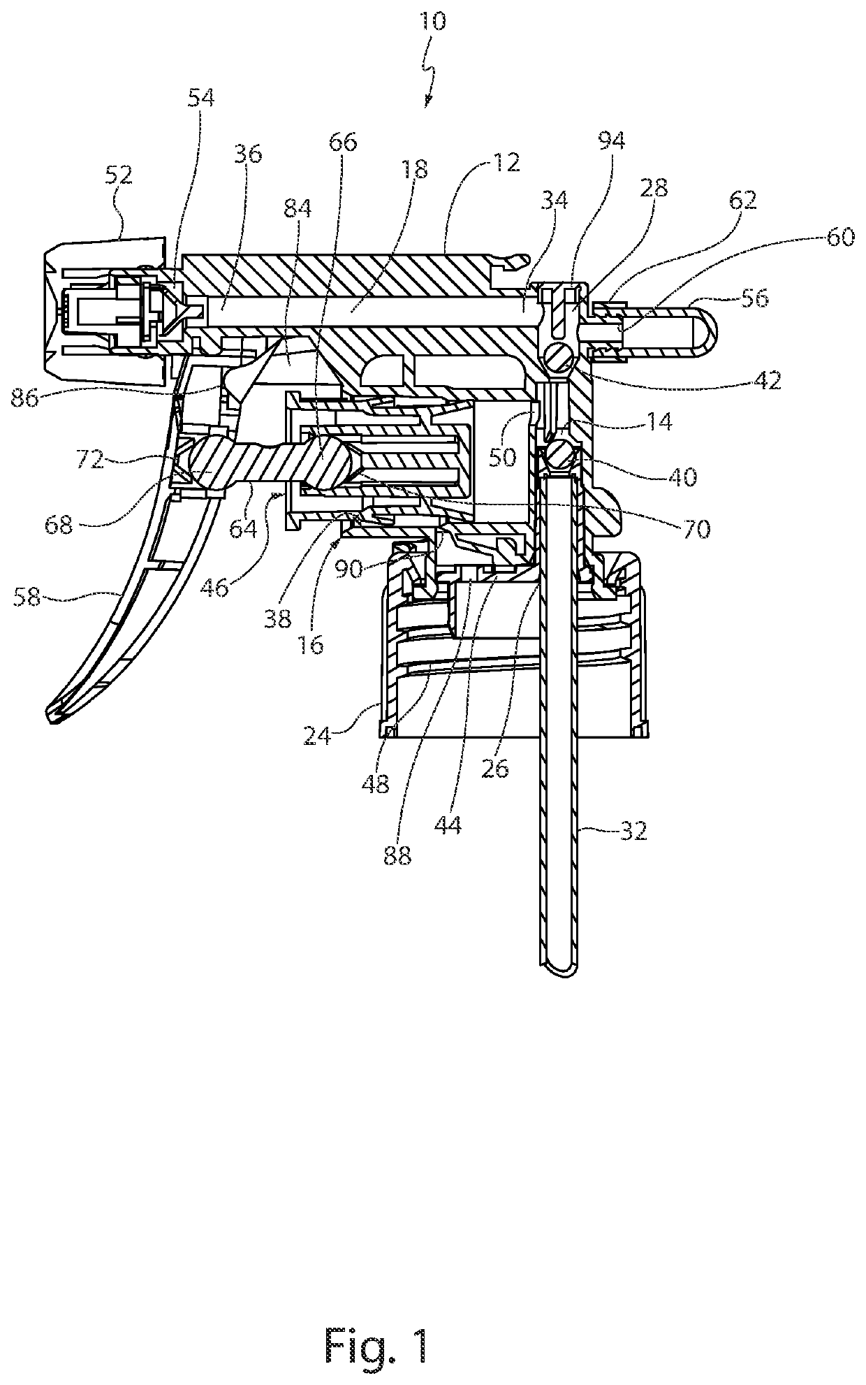
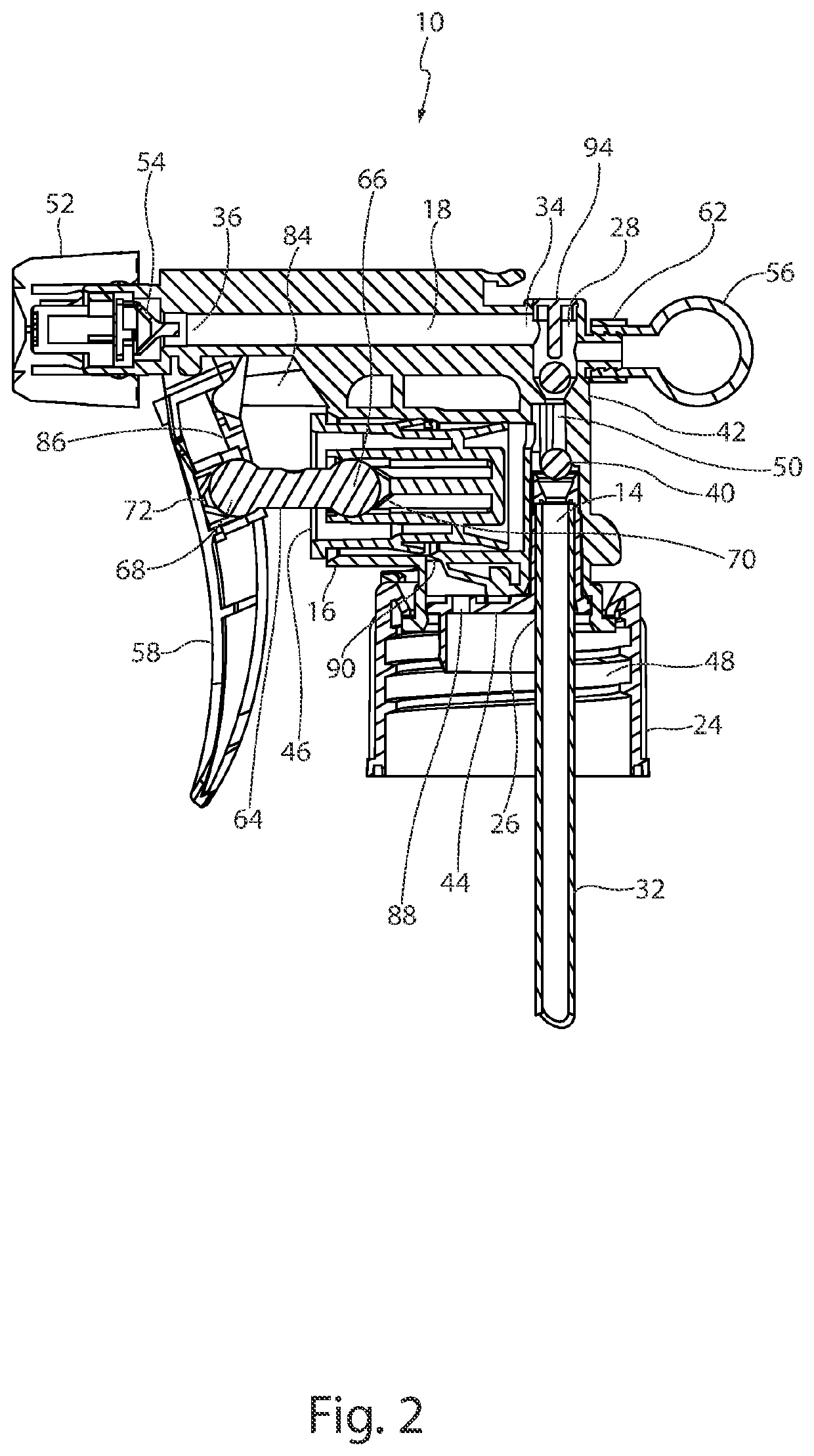
[0029]As discussed above, the trigger sprayer of the present invention 10 provides a trigger sprayer design that stores a quantity of pressurized liquid during the charge stroke of the trigger for subsequent release during the return stroke. Consequently, an appreciable volume of liquid is dispensed during both the charge and the return strokes of the trigger creating a continuous discharge stream of fluid. The trigger sprayer of the present invention ...


PUM


Abstract

A manually operated trigger sprayer that stores a quantity of pressurized liquid during the charge stroke of the trigger for subsequent release during the return stroke, is presented. The trigger sprayer is configured such that an appreciable volume of liquid is dispensed during both the charge and the return strokes of the trigger, creating a continuous discharge stream, for so long as the trigger is actuated. The present invention trigger sprayer also provides an all plastic construction by replacing the metal coil spring of prior art trigger sprayers with a U-shaped plastic spring located exterior to the pump housing thereby making the trigger sprayer well-suited for recycling.

Description

CROSS-REFERENCES TO RELATED APPLICATION[0001]This application claims the benefit of U.S. Provisional Application Ser. No. 63 / 170,544, filed Apr. 4, 2021 and entitled “All Plastic Continuous Spray Trigger,” which is incorporated herein by this reference.BACKGROUND OF THE INVENTIONField of the Invention[0002]The present invention relates to hand held and hand operated liquid dispensing pumps commonly referred to as trigger sprayers.Background Art[0003]The present invention pertains to trigger sprayers which are connectable to a separate dispenser container containing a liquid. The trigger sprayers have a hand operated trigger that is used to operate a pump in the sprayer. The pump draws liquid from the dispenser container and dispenses it through a nozzle via a liquid flow path. A pressure regulating valve within the liquid flow path and downstream of the pump prevents the flow of liquid to the nozzle until the liquid is raised to at least a minimum fluid pressure level. When the flui...

Claims


Application Information

Patent Timeline
Patent Type & Authority Patents(United States)
IPC IPC(8): B05B11/00
CPCB05B11/304B05B11/3057B05B11/0008B05B11/0064B05B11/0075B05B11/1011B05B11/104B05B11/1067B05B11/1057
Inventor ARMINAK, ARMIN
Owner ARMINAK ARMIN
Features
  • Generate Ideas
  • Intellectual Property
  • Life Sciences
  • Materials
  • Tech Scout
  • Unparalleled Data Quality
  • Higher Quality Content
  • 60% Fewer Hallucinations
Learn More