Pneumatic tire

a technology of pneumatic tires and pneumatic cylinders, which is applied to tire sidewalls, vehicle components, and without separate inflatable inserts, etc., can solve the problems of limited and insufficient reduction effect of tire weight, and achieve the effect of reducing tire weight, maintaining air permeation preventive properties, and good compatibility

Active Publication Date: 2022-11-15
THE YOKOHAMA RUBBER CO LTD
View PDF16 Cites 0 Cited by
  • Summary
  • Abstract
  • Description
  • Claims
  • Application Information

AI Technical Summary

Benefits of technology

[0005]The present technology provides a pneumatic tire including partial tie rubber layers selectively disposed in regions in an area between a carcass layer and an inner liner layer, the pneumatic tire having a further reduced tire weight while maintaining air permeation preventive properties and steering stability, to achieve good compatibility between these qualities.
[0007]In the present technology, partial tie rubber layers are used, and the length of intrusion L1 and the length of protrusion L2 from the perpendicular line P (i.e., the outermost edge of the belt layers in the tire lateral direction) are set as described above to reduce the tire weight more than those of a known pneumatic tire including a full tie rubber layer. Thus, the partial tie rubber layers can cover a minimum area required for achieving air permeation preventive properties and steering stability at a level similar to that of a known pneumatic tire, and excellent air permeation preventive properties and steering stability can be maintained. Here, the area covered with the partial tie rubber layers in order to achieve these qualities is minimized and thus the volume of the partial tie rubber layers can be significantly reduced in comparison with a known pneumatic tire including partial tie rubber layers. Thus, the tire weight can be further reduced. In this way, good compatibility between the air permeation preventive properties, the steering stability, and the reduction in tire weight can be achieved.
[0009]According to the present technology, it is preferred that the hardness of the rubber of the partial tie rubber layers be within the range from 50 to 70. This can supplement the rigidity of the sidewall portions that may decrease as the volume of the partial tie rubber layers decreases and thus is advantageous in maintaining the steering stability. In the present technology, “hardness of rubber” is defined as the hardness measured with a type A durometer in accordance with JIS (Japanese Industrial Standard) K6253 at a temperature of 20° C. (referred to as JIS-A hardness).

Problems solved by technology

Even when tie rubber layers are provided in parts (when partial tie rubber layers are used) as in the propositions described above, the effect on reduction in tire weight is limited and not necessarily sufficient because the performance level equivalent to that of a known full tie rubber layer (air permeation preventive properties and steering stability on a dry road surface) has to be maintained.

Method used


Image

  • Pneumatic tire
  • Pneumatic tire

Examples


examples

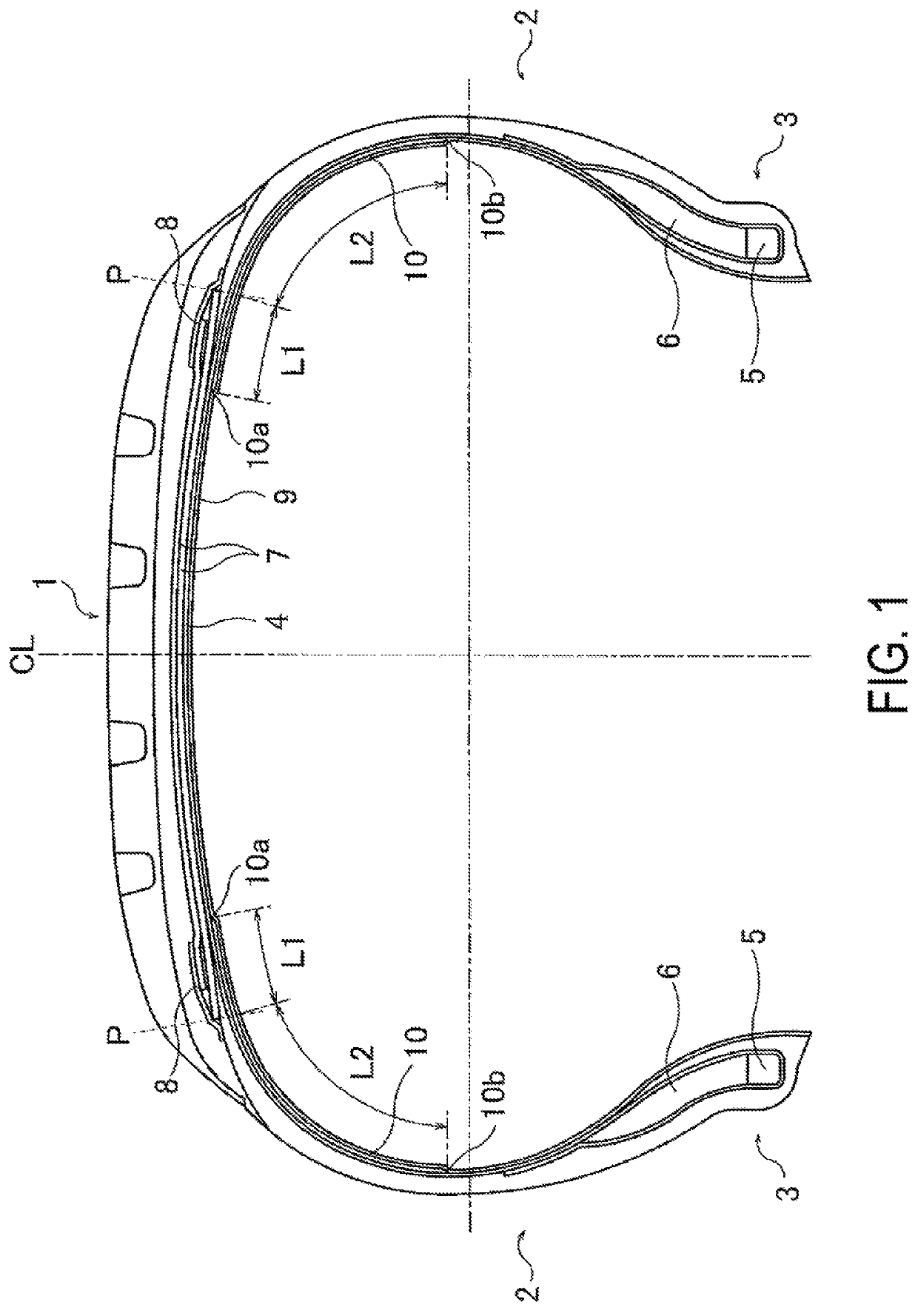
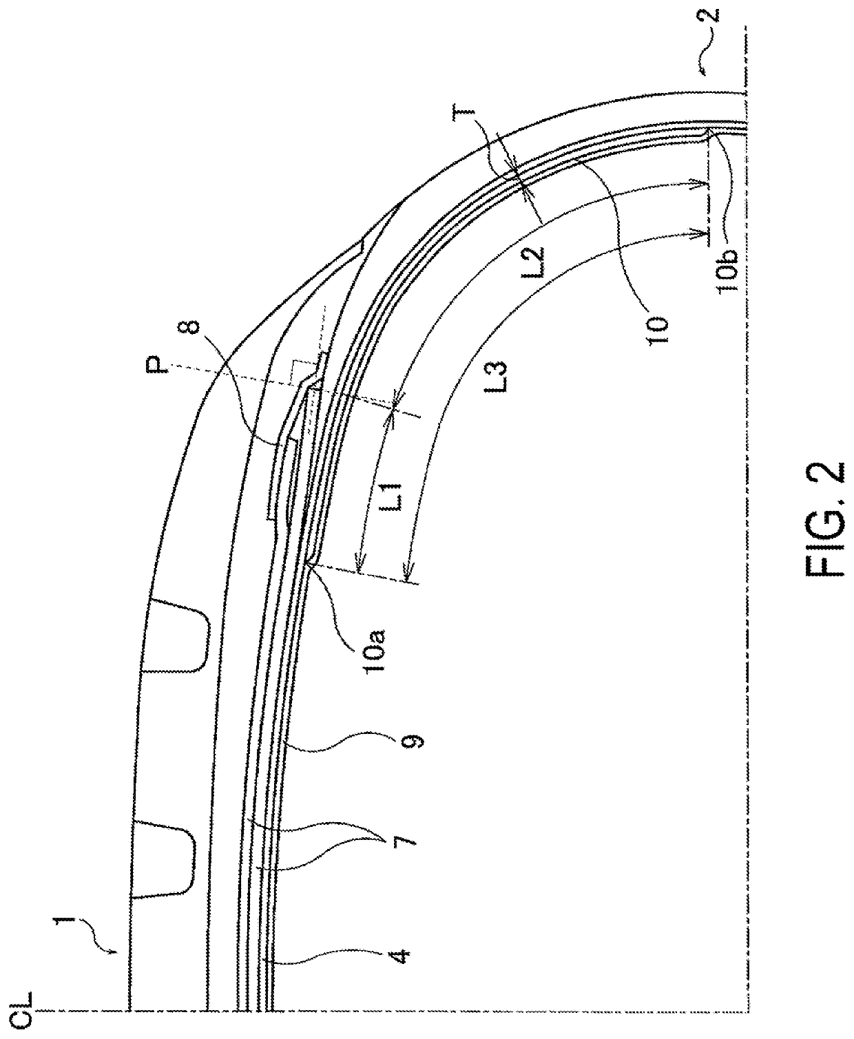
[0026]Fifty six types of pneumatic tires according to Conventional Example 1, Comparative Examples 1 to 11, and Examples 1 to 44 were manufactured to have a tire size of 195 / 65R15, a basic structure illustrated in FIG. 1, and a structure of a tie rubber layer, a length of intrusion L1 from a perpendicular line P extending from the outermost edge of belt layers in the tire lateral direction through an inner liner layer toward a tire equator of each partial tie rubber layer, a length of protrusion L2 from the perpendicular line P of the belt layers toward a bead portion of the partial tie rubber layer, a periphery length L3 of the partial tie rubber layer, a hardness of the rubber composition of the partial tie rubber layer, and a rubber thickness T of the partial tie rubber layer as specified in Tables 1 to 5.

[0027]In the “Structure of tie rubber layer” fields in Tables 1 to 5, a full tie rubber layer is indicated as “full” and a partial tie rubber layer is indicated as “partial”. In...


PUM

PropertyMeasurementUnit
lengthaaaaaaaaaa
lengthaaaaaaaaaa
lengthaaaaaaaaaa

Abstract

Provided is a pneumatic tire. A partial tie rubber layer is selectively disposed between a carcass layer and an inner liner layer in an area on a tread portion on either side in a tire lateral direction excluding a center region of the tread portion such that a length of intrusion from a perpendicular line extending from an outermost edge of a belt layer in a tire lateral direction through the inner liner layer toward a tire equator of each of the partial tie rubber layers is within the range from 0 to 15 mm and a length of protrusion from the perpendicular line toward a bead portion of the partial tie rubber layer is within the range from 15 to 120 mm.

Description

TECHNICAL FIELD[0001]The present technology relates to a pneumatic tire including partial tie rubber layers selectively disposed in regions in an area between a carcass layer and an inner liner layer, and particularly relates to a pneumatic tire having a reduced tire weight while maintaining air permeation preventive properties and steering stability to achieve good compatibility between these qualities.BACKGROUND ART[0002]In a typical pneumatic tire, a tie rubber layer is disposed between a carcass layer and an inner liner layer to prevent carcass cords from intruding into the inner liner layer when an unvulcanized tire is inflated during production. For such a tie rubber layer, it has been proposed to use partial tie rubber layers selectively disposed in regions in the entire area between the carcass layer and the inner liner layer, to reduce tire weight and rolling resistance (for example, refer to Japan Patent Nos. 5239507 and 5723086).[0003]Such partial tie rubber layers are di...

Claims


Application Information

Patent Timeline
Patent Type & Authority Patents(United States)
IPC IPC(8): B60C9/08B60C5/14B60C9/04B60C13/04
CPCB60C9/08B60C5/14B60C5/142B60C9/04B60C13/04
Inventor AKASHI, YASUTAKA
Owner THE YOKOHAMA RUBBER CO LTD
Why Eureka
Try Eureka