System and method for reducing noise and/or vibration in a cleaning apparatus with combing unit for removing debris

a technology of cleaning apparatus and debris, which is applied in the direction of mechanical suction control, suction cleaners, brushes, etc., can solve the problems of debris (e.g., hair) that becomes entangled around the roller, air that stops flowing into the suction conduit, and damage to the suction motor

Active Publication Date: 2022-11-22
SHARKNINJA OPERATING LLC
View PDF41 Cites 0 Cited by
  • Summary
  • Abstract
  • Description
  • Claims
  • Application Information

AI Technical Summary

Benefits of technology

[0006]One solution to generally reduce and / or prevent debris from becoming entangled around the roller is to include a debriding rib. The debriding rib may include a plurality of teeth that contact and cut the debris on the roller as the roller rotates past the debriding rib. In some embodiments, a portion of the roller may also contact the plurality of teeth of the debriding rib. While the debriding rib is effective at generally reducing and / or preventing debris from becoming entangled around the roller, the contact between the roller and the plurality of teeth of the debriding rib may cause unwanted noise and / or vibration. As such, there exists a need for device that can generally reduce and / or prevent debris from becoming entangled around the roller while also minimizing and / or eliminating undesired noise and / or vibration.

Problems solved by technology

One of the challenges with vacuum cleaner design is to control engagement of the suction conduit with a surface being cleaned to provide the desired amount of suction.
If the suction conduit is directly engaged with the surface and thus sealed on all sides, air will stop flowing into the suction conduit and the suction motor may be damaged as a result.
If the agitator in the suction conduit is unable to loosen the debris or if the debris is too small, the suction conduit may pass over the debris without removing the debris from the surface.
One challenge with a leading roller in particular is the debris (e.g., hair) that becomes entangled around the roller.
Projections may be used to engage the roller to facilitate removal of debris, but existing structures are often not effective and / or interfere with the operation of the surface cleaning head.
While the debriding rib is effective at generally reducing and / or preventing debris from becoming entangled around the roller, the contact between the roller and the plurality of teeth of the debriding rib may cause unwanted noise and / or vibration.

Method used


Image

  • System and method for reducing noise and/or vibration in a cleaning apparatus with combing unit for removing debris
  • System and method for reducing noise and/or vibration in a cleaning apparatus with combing unit for removing debris
  • System and method for reducing noise and/or vibration in a cleaning apparatus with combing unit for removing debris

Examples


Embodiment Construction

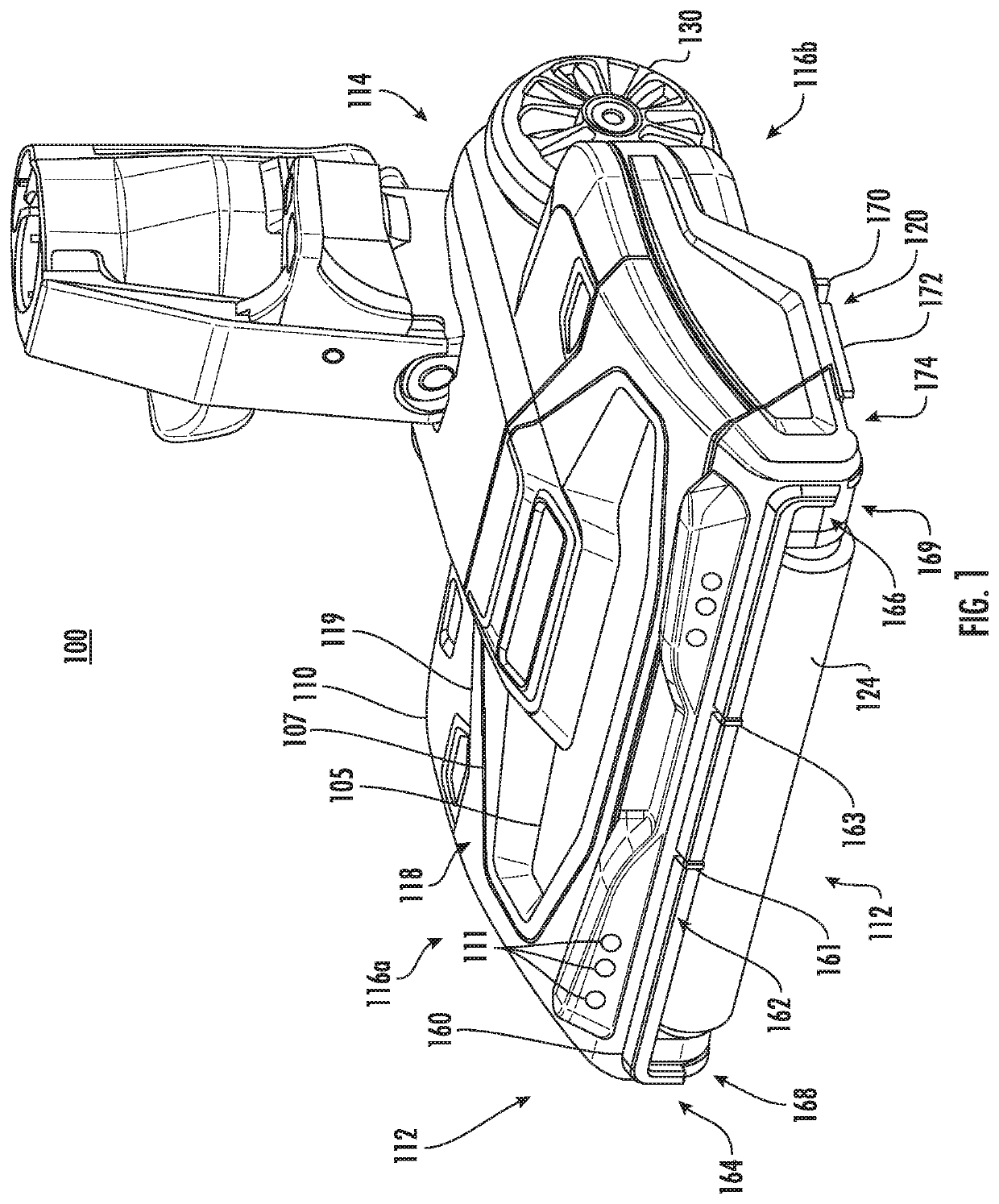
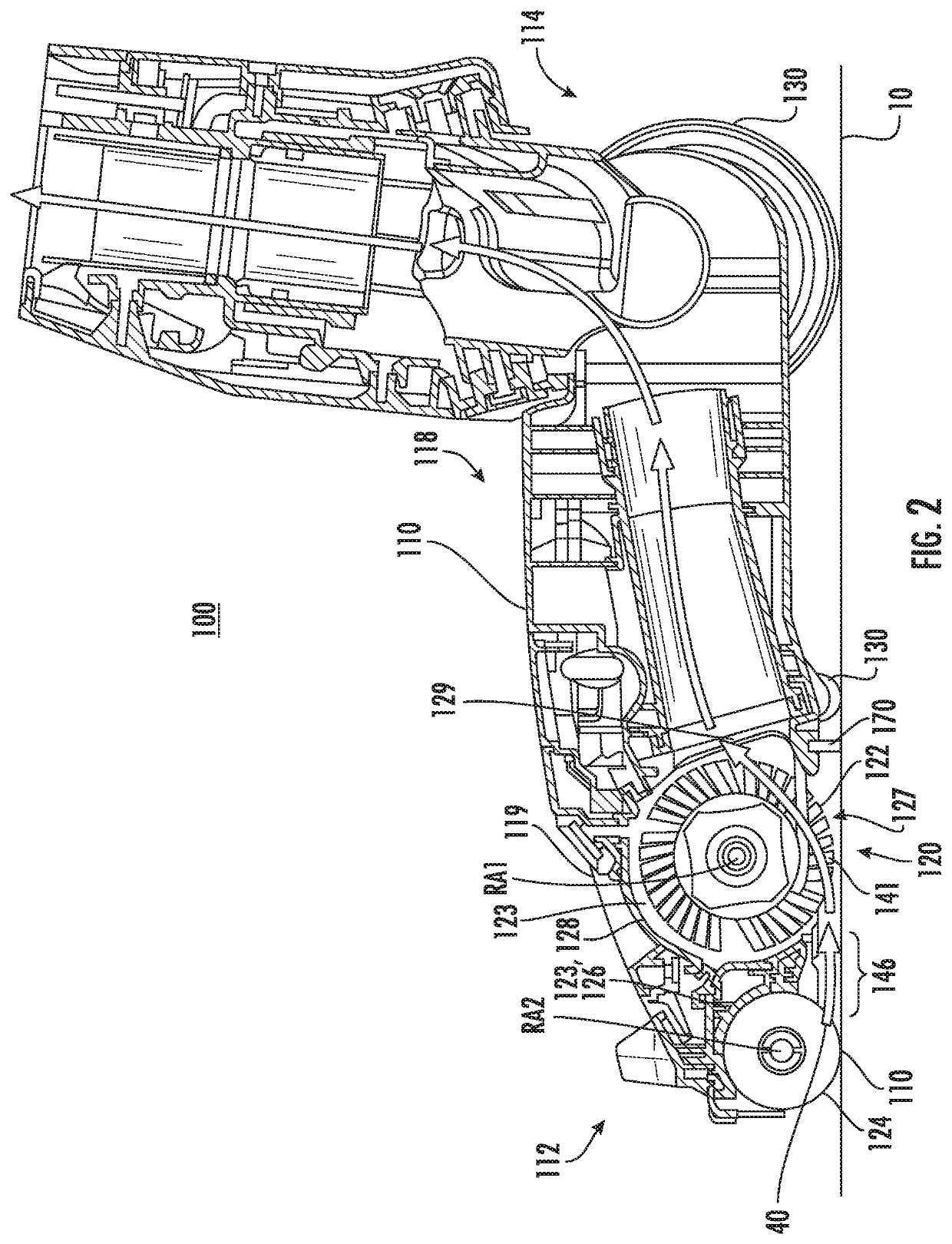
[0032]Although specific embodiments of a surface cleaning head with a leading roller are shown, other embodiments of a cleaning apparatus with a combing unit are within the scope of the present disclosure. The cleaning apparatus may include any types of vacuum cleaner including, without limitation, an “all in the head” type vacuum, upright vacuum cleaners, canister vacuum cleaners, stick vacuum cleaners, robotic vacuum cleaners and central vacuum systems, and may be used in sweepers (e.g., low or no suction). The cleaning apparatus and / or surface cleaning head with a leading roller may also include removable agitators (e.g., brush rolls) in openable agitator chambers, such as the type described in greater detail in U.S. Pat. No. 9,456,723 and U.S. Patent Application Pub. No. 2016 / 0220082, which are commonly-owned and fully incorporated herein by reference. The leading roller may be similarly removable.

[0033]As used herein, a “surface cleaning head” refers to a device configured to c...


PUM


Abstract

A cleaning apparatus may include at least one isolator configured to absorb mechanical vibration generated by contact between an agitator and a combining unit to reduce noise and / or vibration. The isolator may include at least one combing isolator disposed at least partially between the combing unit and the surface cleaning head. Alternatively (or in addition), the isolator may include a panel isolator disposed at least partially between a housing of the cleaning apparatus and a panel.

Description

CROSS-REFERENCE TO RELATED APPLICATIONS[0001]The present application claims the benefit of U.S. Provisional Patent Application Ser. No. 62 / 717,309 filed on Aug. 10, 2018 and U.S. Provisional Patent Application Ser. No. 62 / 851,294 filed on May 22, 2019, both of which are fully incorporated herein by reference.TECHNICAL FIELD[0002]The present disclosure relates to a cleaning apparatus, such as a surface cleaning head for a vacuum cleaner, with a combing unit for removing debris from a cleaning roller, and more particularly for systems and method for reducing noise and / or vibration in such systems.BACKGROUND INFORMATION[0003]Vacuum cleaners generally include a suction conduit with an opening on the underside of a surface cleaning head for drawing air (and debris) into and through the surface cleaning head. One of the challenges with vacuum cleaner design is to control engagement of the suction conduit with a surface being cleaned to provide the desired amount of suction. If the suction...

Claims


Application Information

Patent Timeline
Patent Type & Authority Patents(United States)
IPC IPC(8): A47L9/00A47L9/04A47L9/06
CPCA47L9/0081A47L9/04A47L9/06A47L9/0477A47L5/30A47L9/02A47L9/30A47L9/0072A47L9/28A46B13/006A46B13/001
Inventor FREESE, JOHN B.SMITH, TYLER S.GAO, WENXIULIU, IANSARDAR, NICHOLAS
Owner SHARKNINJA OPERATING LLC
Why Eureka
Try Eureka