
Hand-guided grinding or sanding device

a technology of sanding device and guide rod, which is applied in the direction of metal sawing accessories, portable power tools, manufacturing tools, etc., can solve the problem of reducing the danger of unsatisfactory grinding, and achieve the effect of reducing the danger of grinding tracks, reducing the danger of grinding, and reducing the risk of grinding

Inactive Publication Date: 2001-06-21
HILTI AG
View PDF0 Cites 29 Cited by
  • Summary
  • Abstract
  • Description
  • Claims
  • Application Information

AI Technical Summary

Benefits of technology

[0005] Therefore it is a primary object of the invention to provide a remedy for these disadvantages in the state of the art. A hand-guided grinding device is provided which can be guided by one hand with little expenditure of force. The danger of grinding tracks, resulting from a tilting of the grinding device, is decreased. At the same time, the device is ready for diversified use for a one-handed or a two-handed operation, for which the user can select the way of holding the grinding device, which is most advantageous for him and the respective application purpose.

Problems solved by technology

This decreases the danger of an unsatisfactory grinding resulting from tilting of the grinding equipment.

Method used


Image

  • Hand-guided grinding or sanding device
  • Hand-guided grinding or sanding device

Examples


Embodiment Construction

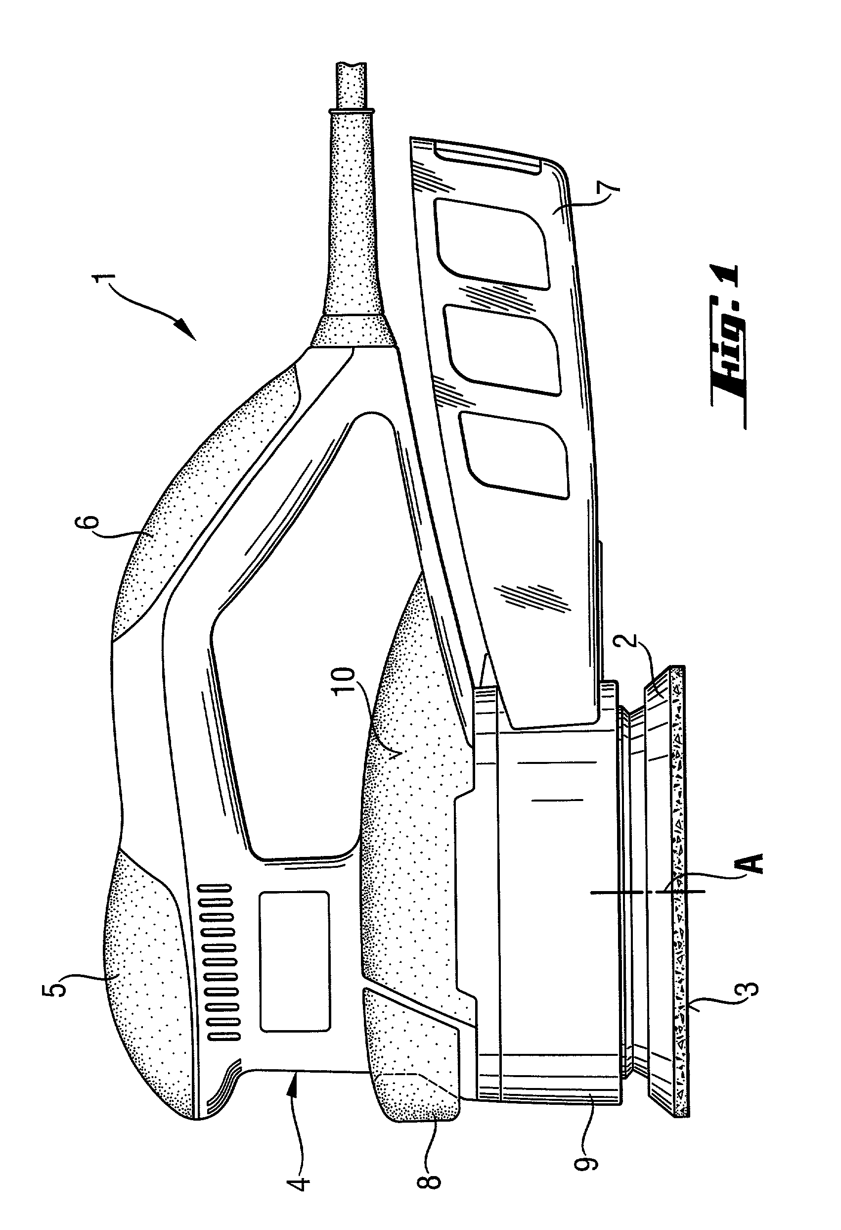
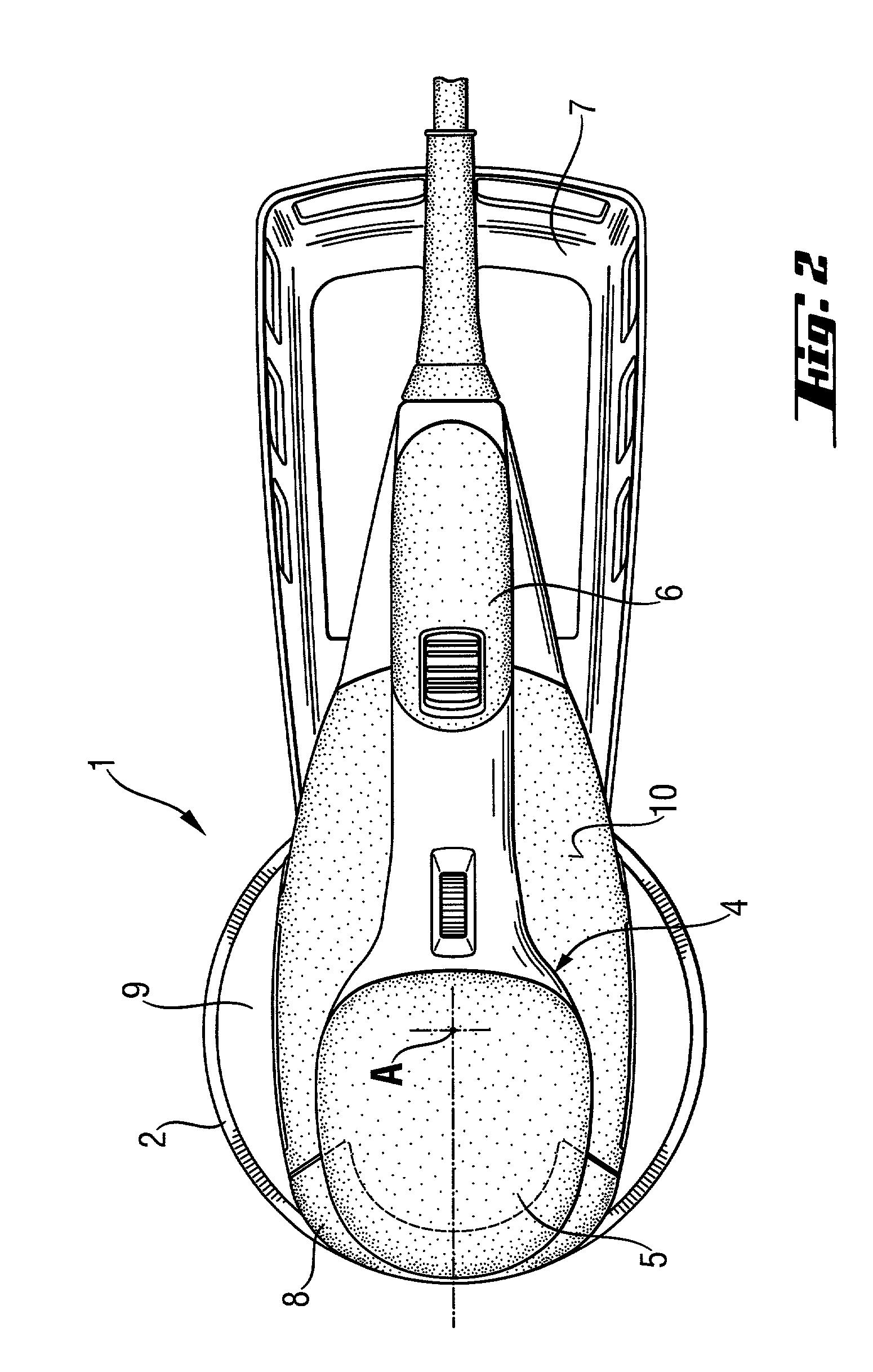
[0020] An embodiment of the invention is shown in FIGS. 1 and 2, as a hand-guided grinding device 1. The grinding device 1 has a central housing 4, from which a motor driven grinding disk 2 extends. The grinding disk 2 is mounted on an axis A on a lower side of the central housing 4. The driving motor, usually an electric motor, the transmission and, optionally, other parts, such as a fan wheel for aspirating dust, are accommodated in the central device housing 4. At one side of the central housing 4, a main handle 6 projects laterally and accommodates the electronics of the device and an actuating switch. The energy is supplied to the grinding device over a supply cable, the details of which are not given and which is fastened to the main handle 6 and can be connected, for example, to the a main supply. At the side of the central housing 4 for the device, opposite the main handle 6, an additional handle 8 for a two-handed operation is disposed. At the upper end section of the centr...


PUM

PropertyMeasurementUnit
average distanceaaaaaaaaaa
distanceaaaaaaaaaa
pressureaaaaaaaaaa

Abstract

A hand-guided grinding device (1) carries out a planar grinding motion and is mounted on a motor-driven grinding disk (2). The grinding disk (2) is mounted on a shaft, extending outwardly from a central housing (4) of the device, located axially above the grinding disk (2) and serving to accommodate a transmission unit and a motor. The grinding device (1) has a main handle (6) and an additional handle (8) for the two-handed operation of the device (1), and the handles (6, 8) project essentially laterally from the central housing (4) of the device at two mutually opposite sides of the central housing (4) of the device. The central housing (4) of the device has a housing section (9), which axially adjoins the grinding disk (2), and projects laterally outwardly from the central housing (4) of the device at least in certain regions and is equipped with a gripping surface (10) for one-handed operation.

Description

FIELD OF THE INVENTION[0001] The invention is directed to a hand-guided grinding or sanding device for carrying out a planar grinding motion and the device is mounted on a grinding disk. The device has a central housing positioned above the grinding disk which is mounted on an axis of a shaft extending downwardly from the central housing. The central housing has a main handle and an additional handle for two-handed operation of the device.BACKGROUND OF THE INVENTION[0002] For working planar, concave or convex surfaces of parts of wood, plastic, plaster and also metal, grinding devices of different constructions are used. The types of grinding devices, most in use, are either orbital sanders or eccentric sanders, for which the part is worked by a grinding or sanding element carrying out a motor-driven, flat grinding motion, in order to eliminate dimensional inaccuracies and, depending on the grinding or sanding element used, achieve a more or less smooth surface.[0003] The housings o...

Claims


Application Information

Patent Timeline
Patent Type & Authority Applications(United States)
IPC IPC(8): B24B23/02B24B23/03B25F5/02
CPCB24B23/02B25F5/02
Inventor LEGNER, ROLANDSCHNEIDER, HEINZ-JOACHIMVOGT, SILVIO
Owner HILTI AG
Learn More