Orthodontic supporting structure

a supporting structure and orthodontic technology, applied in the field of orthodontic supporting structures, can solve the problems of imposing a heavy burden on a patient, imposing considerable mental pain and stress on the patient, and too much to say that the molars do not move at all

Inactive Publication Date: 2001-06-28
DENTSPLY SANKIN KK
View PDF0 Cites 47 Cited by
  • Summary
  • Abstract
  • Description
  • Claims
  • Application Information

AI Technical Summary

Problems solved by technology

It is, however, too much to say that the molars do not move at all.
In such cases, the orthodontic treatment involves complicated movements and techniques for correcting the arrangement of the teeth which would require an extended period of time, imposing a heavy burden on a patient.
An extraoral anchorage orthodontic appliance, however, imposes considerable mental pain and stress on the patient because wearing the extraoral anchorage appliance greatly affects his or her daily life.
In addition, the aforementioned method of relative movement orthodontic treatment is not suited for correcting the position of a single tooth.
Therefore, the treatment i...

Method used


Image

  • Orthodontic supporting structure
  • Orthodontic supporting structure
  • Orthodontic supporting structure

Examples


first embodiment

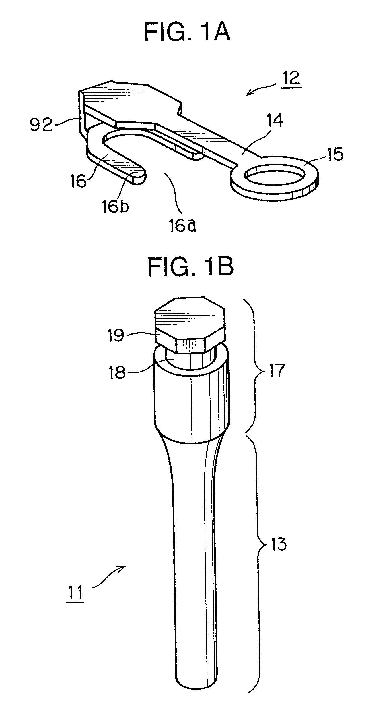
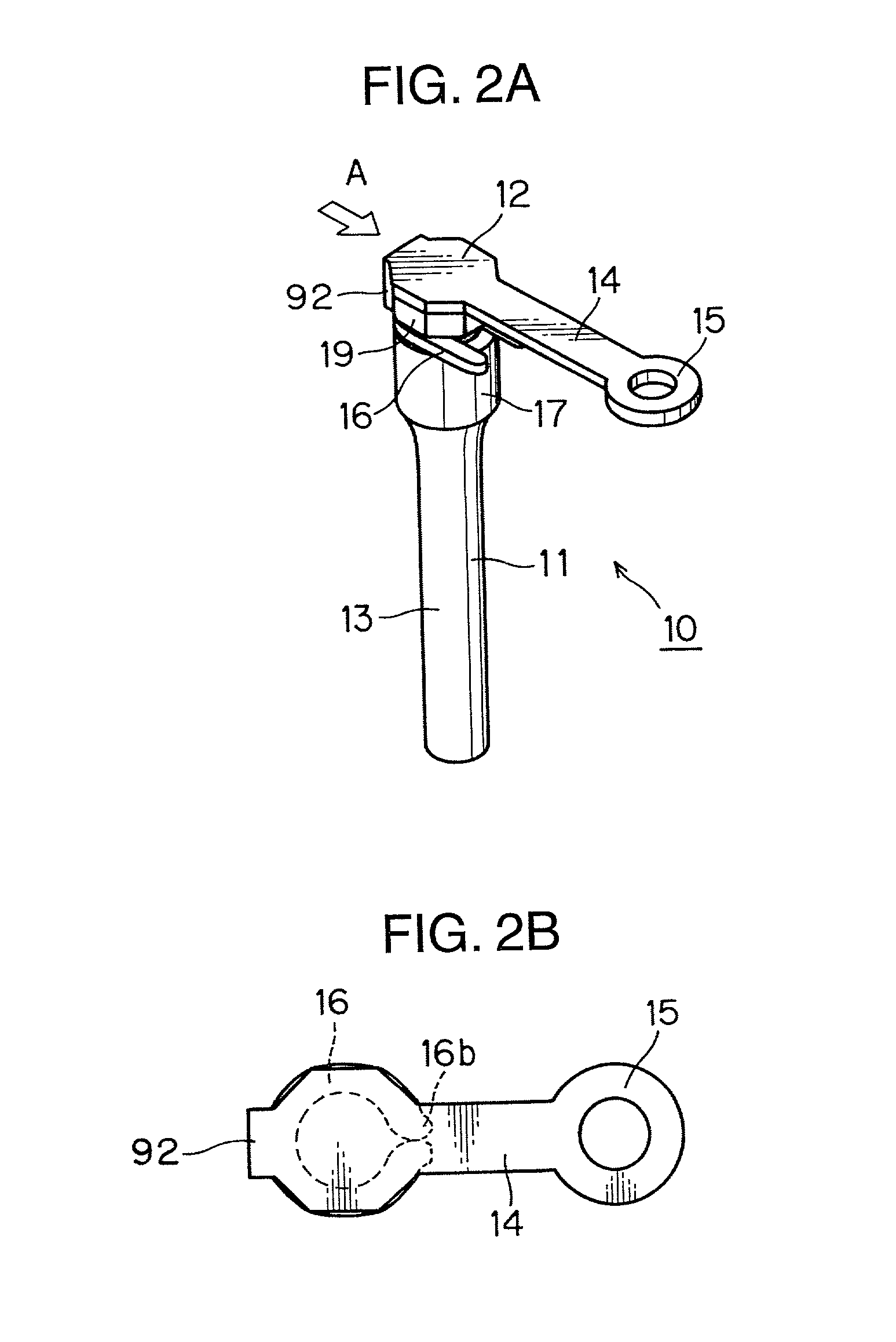
[0069] FIGS. 1A and 1B illustrate an orthodontic supporting structure 10 according to the invention, in which FIG. 1A is a perspective view showing a connecting unit 12 of the support 10 and FIG. 1B is a perspective view showing an implant unit 11 of the support 10. FIGS. 2A and 2B are diagrams illustrating how the connecting unit 12 is fitted to the implant unit 11, in which FIG. 2A is a perspective view showing a situation where the connecting unit 12 is just being fitted to the implant unit 11 and FIG. 2B is a perspective view showing a situation where their assembly has been completed.

[0070] The implant unit 11 includes an upper portion 17 which is exposed to the oral cavity and an embedded portion 13 which is embedded in a jaw bone, wherein a narrow part 18 is formed in the upper portion 17. A head 19 of the upper portion 17 just above the narrow part 18 is shaped into a regular octagon in top view.

[0071] The connecting unit 12 includes an arm 14 which extends into the oral cav...

second embodiment

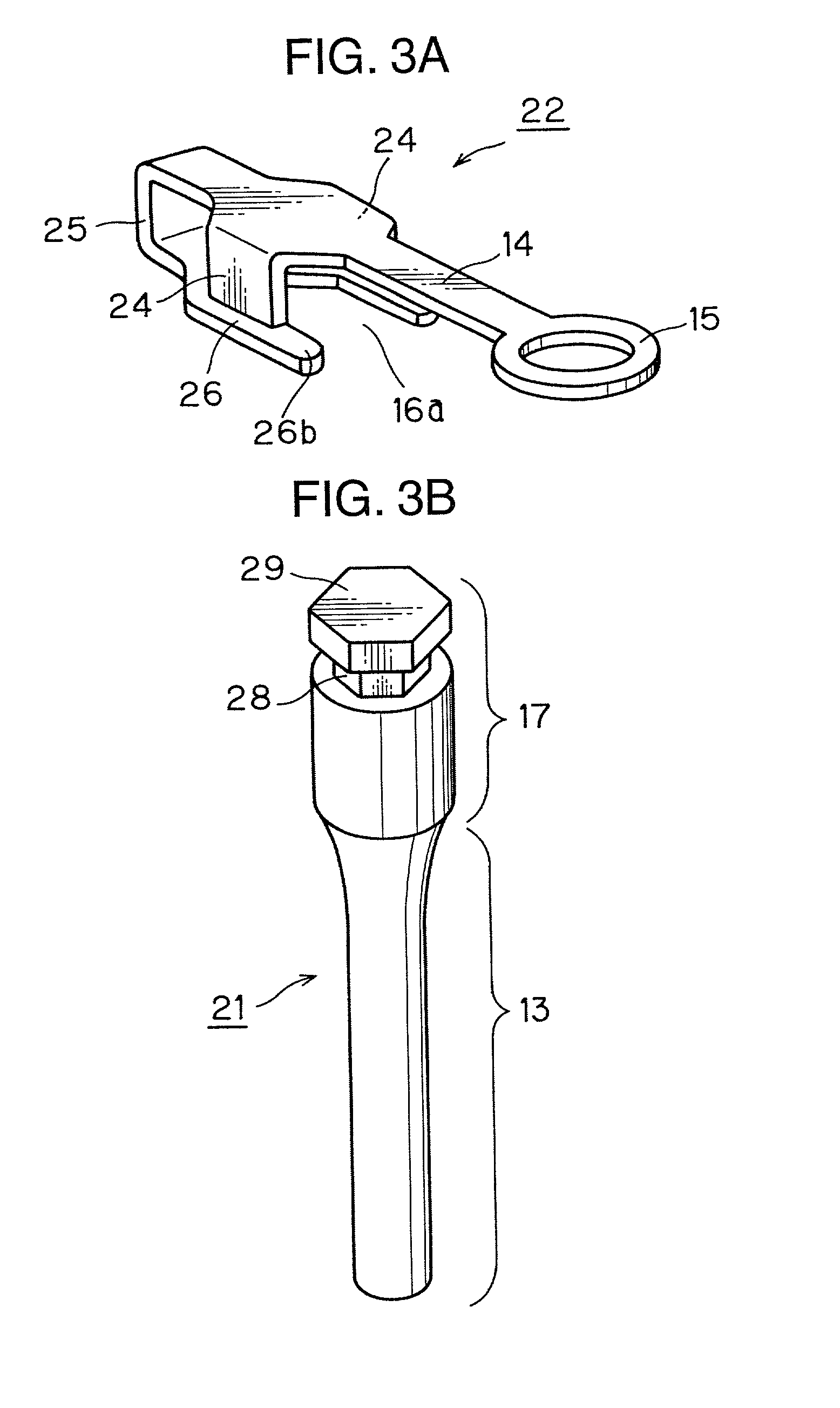
[0078] FIGS. 3A-3B and 4 illustrate an orthodontic supporting structure 20 according to a second embodiment of the invention, in which FIG. 3A is a perspective view showing a connecting unit 22 of the support 20, FIG. 3B is a perspective view showing an implant unit 21 of the support 20, and FIG. 4 is a front view showing how the connecting unit 22 is fitted to the implant unit 21.

[0079] In this embodiment, a narrow part 28 of the implant unit 21 is shaped into a regular hexagon in top view as is a head 29 of an upper portion 17 of the implant unit 21.

[0080] An engaging part 26 of the connecting unit 22 has an opening 16a at one end. This opening 16a has a generally hexagonal inner surface structure having four sides and opening at one end, so that the inner shape of the opening 16a is appropriate to fit on the narrow part 28 of the implant unit 21. The connecting unit 22 has a pair of side flaps 24 extending downward from two opposite sides of a top plate part 23 which goes into co...

third embodiment

[0083] FIGS. 5A-5B are diagrams showing an orthodontic supporting structure 30 according to a third embodiment of the invention, in which FIG. 5A is a top view and FIG. 5B is a side view. In FIGS. 5A-5B, elements identical or equivalent to those shown in FIGS. 1A-1B and 2 are designated by the same reference numerals and a description of such elements is omitted.

[0084] In this embodiment, an embedded portion 33 of an implant unit 31 is externally threaded. A middle part of a head 39 of the implant unit 31 has a hexagonal cross section in top view with upper and lower parts of the head 39 tapering off from the middle part as illustrated. A narrow part 38 of the implant unit 31 has a circular cross section in top view. An engaging part 16 of a connecting unit 12 has an opening 16a at one end and this opening 16a has a semicircular inner surface structure which fits over the narrow part 38 of the implant unit 31.

[0085] The orthodontic supporting structure 30 of the third embodiment all...


PUM


Abstract

An orthodontic supporting structure of the present invention comprises an implant unit (21) which is implanted in a jaw bone and a connecting unit (22) which includes an arm part (14) having a fastening portion (15). The implant unit (21) has a narrow part (18) in its upper portion (17). The connecting unit (22) further includes an engaging part (26) having an opening (16a) at one end. The engaging part (26) can fit on the narrow part (18) of the implant unit (21). The connecting unit (22) can be attached to the implant unit (21) in a simple way by just sliding the engaging part (26) along the narrow part (18) and then crimping far ends (26b) of the engaging part (26).

Description

[0001] 1. Field of the Invention[0002] The present invention relates to supports for correcting abnormal dentition which can serve as supporting points for relocating or moving an improperly positioned tooth in orthodontic treatment.[0003] 2. Description of the Related Art[0004] Orthodontic treatment for correcting irregularities in teeth arrangement, such as crowded teeth, reversed occlusion or inclination of front teeth to the labial side, is getting popular.[0005] One of the most popular methods of orthodontic treatment includes the steps of fixing brackets to surfaces of individual teeth with an adhesive, for instance, passing an arch wire through the brackets, and relatively moving the individual teeth by applying external forces (which may be hereinafter referred to as correcting forces in this Specification), such as pushing, pulling or twisting forces, to the teeth by use of a restoring force caused by the elasticity of the arch wire, so that the teeth would be adjusted to t...

Claims


Application Information

Patent Timeline
IPC IPC(8): A61B17/56A61C7/00A61C7/20A61C8/00
CPCA61C7/00A61C8/0018A61C8/0096
Inventor KANOMI, RYUZONAKAGAWA, KATSUYUKISHIN, YOSHIHARU
Owner DENTSPLY SANKIN KK
Why Eureka
Try Eureka