
Mold assembly for forming ophthalmic lens or lens blank and method of producing the same using the mold assembly

a mold and lens technology, applied in the field of mold assembly for forming ophthalmic lenses or lens blanks, can solve the problems of high-pressure molding, molds formed of resin materials undesirably deteriorating configurational accuracy, and contact lenses obtained by using molds with optical portions that may not have an accurately formed lens surfa

Inactive Publication Date: 2001-07-19
MENICON CO LTD
View PDF0 Cites 3 Cited by
  • Summary
  • Abstract
  • Description
  • Claims
  • Application Information

AI Technical Summary

Benefits of technology

[0013] In the present mold assembly wherein at least one of the first and second molds is a layered mold constituted by a composite sheet in which the metal sheet layer and at least one resin layer are superposed on each other, the layered mold does not suffer from a problem of deteriorated configurational accuracy due to dimensional errors which arise from a shrinkage of a resin material during forming of the conventional resin-made mold. Accordingly, the layered mold which is constituted by each of the at least one of the first and second molds has stable configurational accuracy, so that one of the opposite surfaces of the ophthalmic lens or the lens blank, which is formed by the layered mold and in which the optical potion having an intended optical power is formed, has a high degree of configurational accuracy. The layered mold according to the present invention can be easily formed by effecting a low-pressure press forming or vacuum forming operation on the composite sheet, for instance. Accordingly, the present layered mold can be efficiently and economically formed than the conventional metal mold or the release layer-covered metal mold. In addition, the present layered mold can be formed without requiring expensive equipment as used in forming the conventional resin mold by the high-pressure molding such as injection molding.
[0026] The present method using the mold assembly having the advantages described above permits easy and economical formation of the ophthalmic lens whose optical surface has a high degree of configurational accuracy and which exhibits the intended optical characteristics, or the lens blank that gives such an ophthalmic lens. Since the layered mold of the mold assembly used in the present method can be repeatedly used, the cost for manufacture of the mold assembly is effectively reduced, and the cost for forming the ophthalmic lens or the lens blank is accordingly reduced.

Problems solved by technology

The male and female molds formed of the resin material undesirably have deteriorated configurational accuracy due to dimensional errors which arise from the shrinkage of the resin material during forming of the resin molds.
In this case, the contact lens obtained by using those molds may not have an accurately formed lens surface whose optical portion has an intended optical power.
Such high-pressure molding, however, undesirably and inevitably requires expensive equipment.
In addition, the molds are likely to be deformed upon removal or releasing of the molded contact lens therefrom, making it difficult to repeatedly use the molds in subsequent molding operations.
The above-described mold assembly, however, does not solve the problems of low efficiency and economy of manufacture of such a metal mold.
If the thickness of the webs is relatively small, the male and female molds formed in the thin webs undesirably tend to be deformed during the molding operation for forming the contact lens.
In this case, the contact lens molded in the deformed male and female molds may not have the intended optical characteristics with high accuracy.

Method used


Image

  • Mold assembly for forming ophthalmic lens or lens blank and method of producing the same using the mold assembly
  • Mold assembly for forming ophthalmic lens or lens blank and method of producing the same using the mold assembly
  • Mold assembly for forming ophthalmic lens or lens blank and method of producing the same using the mold assembly

Examples


Embodiment Construction

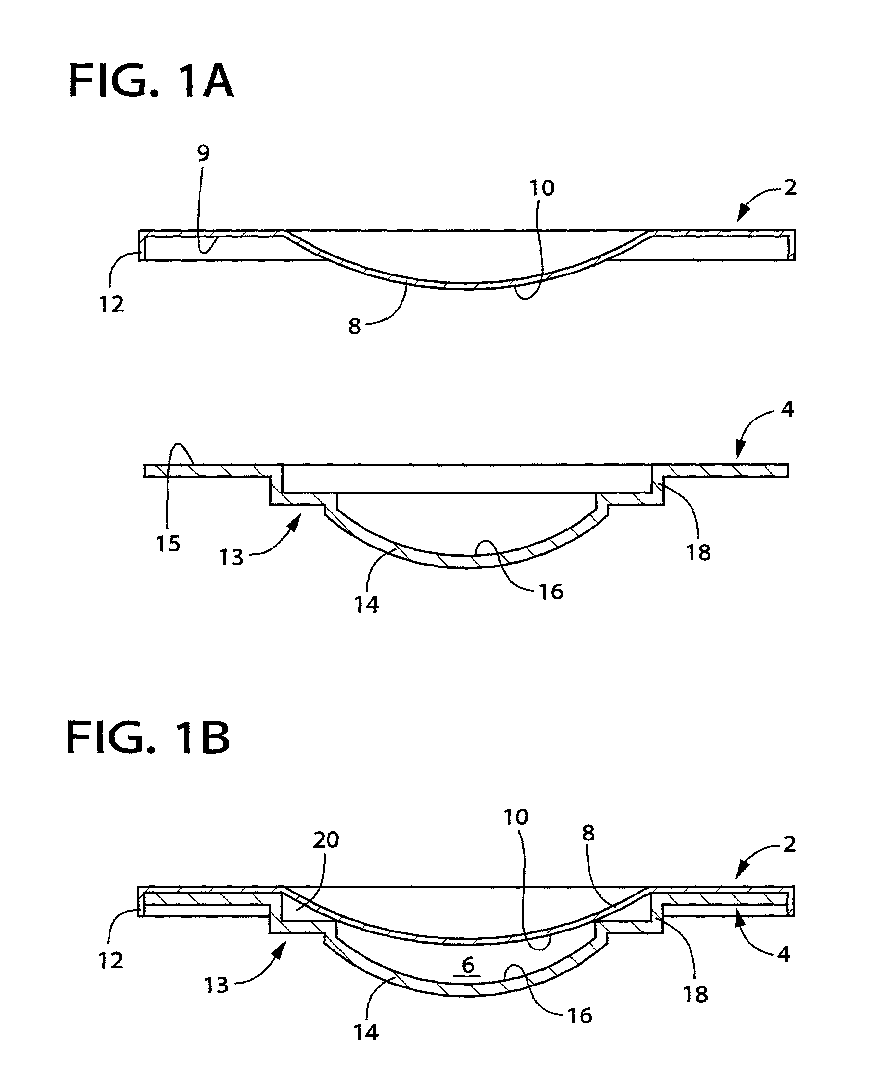
[0033] Referring first to FIGS. 1A and 1B, there is shown a mold assembly for forming an ophthalmic lens or a lens blank, which mold assembly is constructed according to one embodiment of the present invention. The mold assembly shown FIGS. 1A and 1B consists of a first mold in the form of a male mold 2 and a second mold in the form of a female mold 4. As shown in FIG. 1B, the male and female molds 2, 4 are assembled together to define therebetween a mold cavity 6 whose profile follows that of an intended ophthalmic lens, e.g., a contact lens in this embodiment.

[0034] The male mold 2 is a generally disc-shaped member, and has a protruding portion 8 which protrudes downwardly from its central portion as seen in FIG. 1A and which has a curved convex configuration. A central portion of the lower surface of the protruding portion 8 serves as a molding surface 10 (lens-forming surface) for forming a back surface (i.e., base curved surface) of the intended contact lens. The base curve-mol...


PUM

PropertyMeasurementUnit
thicknessaaaaaaaaaa
thicknessaaaaaaaaaa
thicknessaaaaaaaaaa

Abstract

A mold assembly for forming an ophthalmic lens, or a lens blank from which one ophthalmic lens is produced by effecting a cutting operation on at least one of a front surface and a back surface of the lens blank, the mold assembly consisting of a first mold having a molding surface and a second mold having a molding surface, which first and second molds are assembled together so as to define therebetween a mold cavity having a profile corresponding to that of the ophthalmic lens or the lens blank, the mold cavity being filled with a polymeric material which is polymerized to form the ophthalmic lens or the lens blank, wherein at least one of the first and second molds is a layered mold which is constituted by a composite sheet comprising a metal sheet layer and at least one resin layer which are laminated on each other, the at least one resin layer of the composite sheet providing the molding surface of the layered mold which partially defines the mold cavity.

Description

[0001] This application is based on Japanese Patent Application No. 2000-007900 filed Jan. 17, 2000, the contents of which are incorporated hereinto by reference.[0002] 1. Field of the Invention[0003] The present invention relates to a mold assembly for forming an ophthalmic lens or a lens blank, and a method of producing the same using the mold assembly. More particularly, the present invention is concerned with such a mold assembly which is suitably used for forming the ophthalmic lens such as a contact lens or an intraocular lens, or the lens blank from which one ophthalmic lens is produced by effecting a cutting operation on at least one of front and back surfaces of the lens blank, the mold assembly having a structure which assures a high degree of forming accuracy and which is economical to manufacture with relatively inexpensive equipment. The present invention is also concerned with a method of forming the ophthalmic lens or lens blank using the mold assembly, at a reduced c...

Claims


Application Information

Patent Timeline
Patent Type & Authority Applications(United States)
IPC IPC(8): B29C33/38B29C39/26B29D11/00G02C7/04
CPCB29C33/38B29D11/00432B29D11/00548B29L2011/0016Y10S425/808
Inventor TANAKA, YUKIKOSAKA, CHIKAI
Owner MENICON CO LTD
Learn More