Waterproof connector

a multi-polar, waterproof connector technology, applied in the direction of coupling device connection, coupling base/case, securing/insulating coupling contact member, etc., can solve the problem of not achieving the desired level of sealing performance, the connector housing 102 is large in size, and the pitch x of the terminal to the terminal is limited

Inactive Publication Date: 2001-07-26
YAZAKI CORP
View PDF0 Cites 8 Cited by
  • Summary
  • Abstract
  • Description
  • Claims
  • Application Information

AI Technical Summary

Benefits of technology

[0010] In this waterproof connector, since the diameter of the rubber plug accommodating recessed portions of the outer housing can be minimized irrespective of the size of the terminal accommodating chambers of the inner housing, the terminal-to-terminal's pitch becomes small with the result that it is possible to miniaturize a multipolar connector housing (which is composed of the inner housing and the outer housing). Also, since the rubber plugs are not exposed to the outside from the one wall portion of the outer housing, the degradation of the sealing performance of the rubber plugs due to an external force does not occur, with the result that the reliability on the waterproofness effected with the rubber plugs is enhanced.
[0012] In this waterproof connector, the rubber plug guiding portion off the inner housing, the tapered surface on an inlet side of the rubber plug accommodating recessed portion of the outer housing, the tapered surface of the rubber plug, and the electric wire serve and operate as guides, whereby the rubber plug is accommodated reliably in a simple way in the rubber plug accommodating recessed portion of the outer housing. As a result, the reliability on the waterproofness effected with the rubber plugs is further enhanced.
[0014] In this method of assembling a waterproof connector, a small-in-size and multipolar waterproof connector having excellent waterproofness is assembled smoothly in a simple way and in a short time.
[0016] In this waterproof connector, plug material is injected into each rubber plug accommodating chamber of each row from the plug material injection port of each row, so that the rubber plug can be integrally formed in which an electrical wire insertion port having a plurality of sealing portions tightly coming into contact with the outer circumference of the electrical wire is integrally formed. Therefore, no workers forget to attach the rubber plugs, and sealing can be positively made between each rubber plug accommodating chamber of the connector housing and the rubber plug and also between the rubber plug and the electrical wire. Therefore, the waterproof performance and the waterproof reliability can be enhanced. Due to the foregoing, it becomes unnecessary to provide a process in which the rubber plug is attached to the connector housing when the waterproof connector is assembled. Therefore, the multipolar waterproof connector, the sealing property of which is high, can be assembled in a short period of time, and the entire assembling property can be more enhanced.
[0018] In this waterproof connector, the positions of a plurality of sealing portions in the electrical wire insertion holes of the rubber plugs integrally formed in the rubber plug accommodating chambers in each row are made different from the positions of the plug material injection ports of each row. Therefore, it is possible to prevent the deterioration of the waterproof performance with respect to a plurality of sealing portions in the electrical wire insertion holes of the rubber plug. Accordingly, the waterproof performance and the waterproof reliability of the waterproof connector can be more enhanced.

Problems solved by technology

Therefore, the terminal-to-terminal pitch X is limited with the result that the connector housing 102 has become large in size.
Also, since the rubber plug 108 is exposed from a rear surface side of the connector housing 102 to the outside, the rubber plug 108 is damaged or deformed during high-tension cleaning or due to contact therewith of a machine tool or the like, with the result that a desired level of sealing performance was not obtained.

Method used


Image

  • Waterproof connector
  • Waterproof connector
  • Waterproof connector

Examples


first embodiment

[0047] First embodiment

[0048] FIG. 6 is a cross-sectional view showing a state before a waterproof connector of an first embodiment of the present invention is assembled. FIG. 7 is a partially cross-sectional perspective view showing a state before the waterproof connector is assembled. FIG. 8(a) is a cross-sectional view showing a state before the waterproof connector is assembled. FIG. 8(b) is a cross-sectional view showing a state in which a spacer is engaged with an outer housing of the waterproof connector. FIG. 8(c) is a cross-sectional view showing a state in which an electrical wire is penetrated through the outer housing and spacer. FIG. 8(d) is a cross-sectional view showing a state in which the electrical wire is connected with a terminal accommodated in a terminal accommodating chamber of an inner housing. FIG. 8(e) is a cross-sectional view showing a state in which the waterproof connector has been assembled.

[0049] As shown in FIGS. 6 to 8, the connector housing 11 of t...

second embodiment

[0062] Second Embodiment

[0063] Second embodiment improves the efficiency of the waterproof connector 10 of the first embodiment.

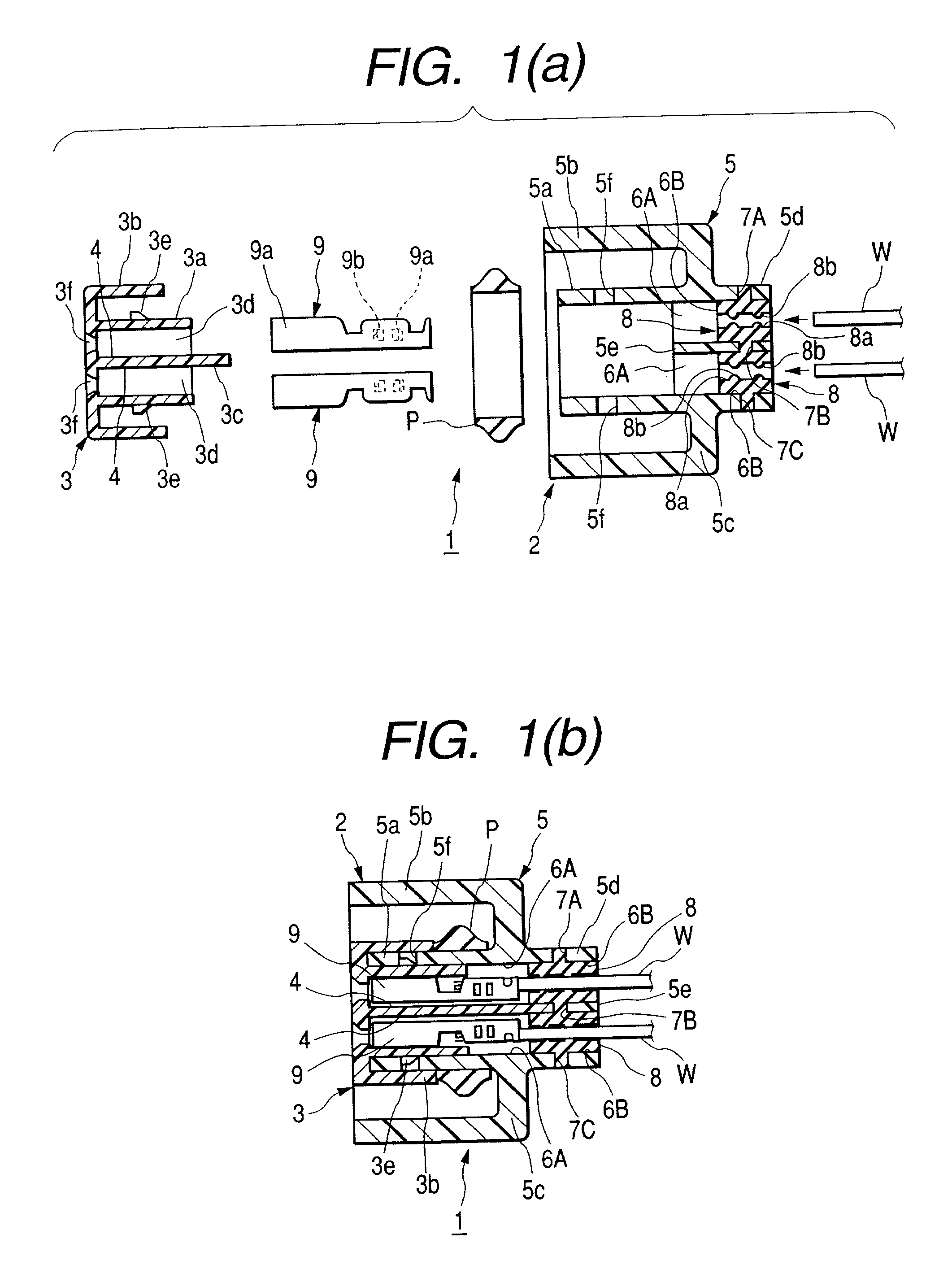
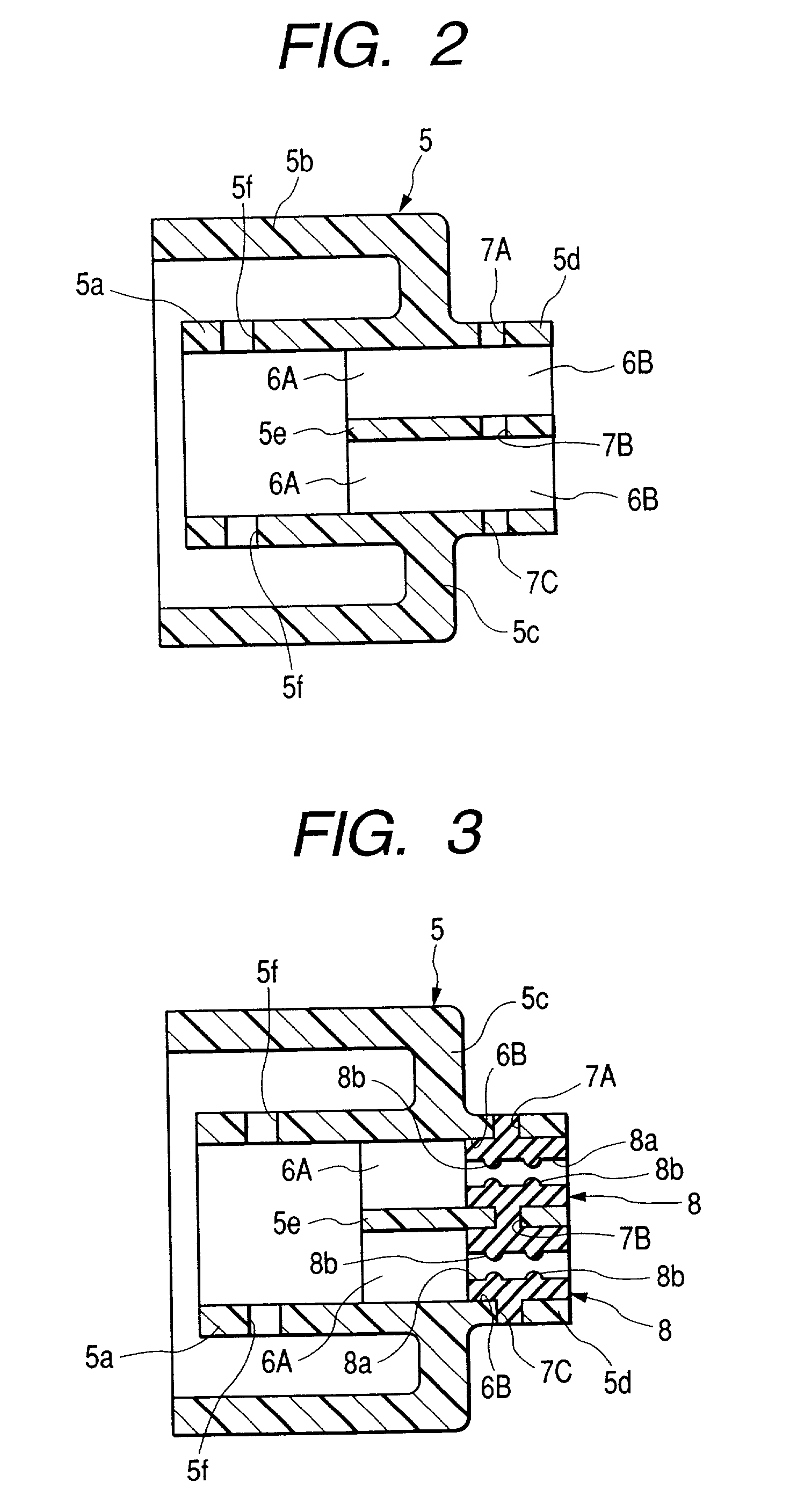
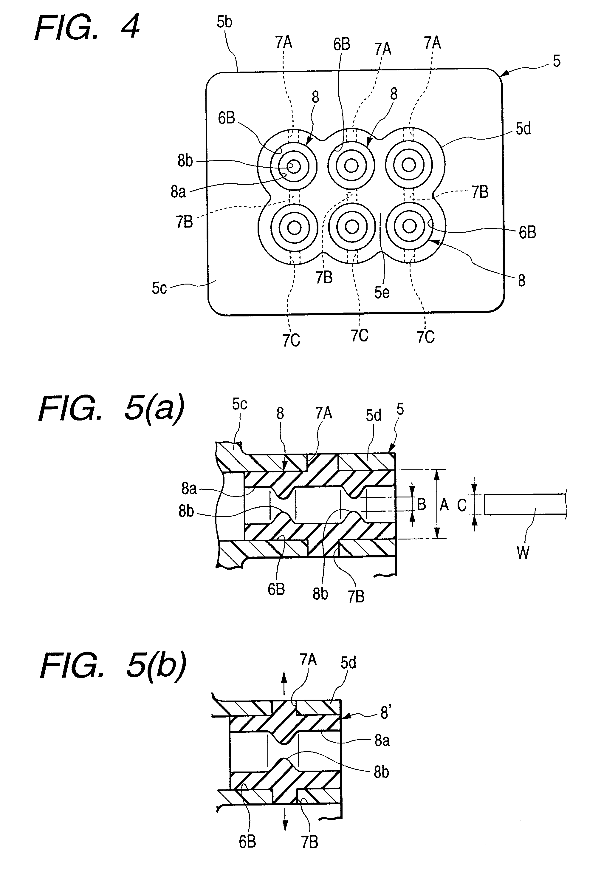
[0064] FIG. 1(a) is a cross-sectional view showing a state of a waterproof connector of an second embodiment of the present invention before it is assembled. FIG. 1(b) is a cross-sectional view showing a state of the waterproof connector after it has been assembled. FIG. 2 is a cross-sectional view of an outer housing used for the waterproof connector. FIG. 3 is a cross-sectional view showing a state in which a rubber plug is integrally formed in the outer housing. FIG. 4 is a rear view of the outer housing in which the rubber plug is integrally formed. FIG. 5(a) is a partially cross-sectional view of a primary portion of an outer housing with which the rubber plug is integrally formed. FIG. 5(b) is a partially cross-sectional view of a comparative example of the primary portion.

[0065] As shown in FIGS. 1(a), 1(b) and 4, the connector housing 2 of the water...


PUM

PropertyMeasurementUnit
outer circumferenceaaaaaaaaaa
circumferenceaaaaaaaaaa
waterproofaaaaaaaaaa

Abstract

A waterproof connector 1 includes: a plurality of terminal accommodating chambers 4, 6A arranged in the vertical and the traverse direction of a connector housing 2; and a plurality of rubber plug accommodating chambers 6B communicated with the terminal accommodating chambers 6A, wherein a rubber plug 8 in which an electrical wire insertion hole 8a is formed is arranged in each rubber plug accommodating chamber 6B, a terminal 9 connected with an electrical wire W is capable of being freely accommodated in each terminal accommodating chamber 4, 6A, a plug material injection port 7A, plug material path 7B and vent hole 7C are serially formed in each row of the rubber plug accommodating chambers 6B in one of the vertical and the traverse direction of the peripheral wall 5d and the partition wall 5e which form the rubber plug accommodating chambers 6B of the connector housing, plug material is injected into the rubber plug accommodating chambers 6B of each row from the plug material injection port 7A of each row so as to integrally form rubber plugs 8 in which electrical wire insertion holes 8a having a plurality of sealing portions 8b closely coming into contact with the outer circumferences of the electrical wires W are formed.

Description

[0001] 1. Technical Field[0002] The present invention relates to a small multipolar waterproof connector in which the waterproof property is enhanced between a connector housing and a plurality of electrical wires connected with terminals.[0003] 2. Related Art[0004] FIG. 9 shows one type of waterproof connector. A connector housing 102 of this waterproof connector 101 has formed therein a plurality of terminal accommodating chambers 103 each of which forms at its rear portion an electric wire sealing chamber 104 so that the sealing chamber 104 is communicated therewith. Also, each terminal accommodating chamber 3 accommodates a female terminal 106 having an electric wire connected thereto with the female terminal 106 being engaged with a lance (flexible engaging arm) 107. Further, each terminal accommodating chamber 103 and its corresponding electric wire 105 are sealed by a rubber plug 108 forced into the electric wire sealing chamber 104.[0005] It is to be noted that similar techn...

Claims


Application Information

Patent Timeline
Patent Type & Authority Applications(United States)
IPC IPC(8): H01R13/52
CPCH01R13/5205
Inventor SUZUKI, SHOGO
Owner YAZAKI CORP
Why Eureka
Try Eureka