Weaving loom for producing a leno fabric

a weaving loom and fabric technology, applied in the direction of looms, leno shedding mechanisms, textiles and papermaking, etc., can solve the problems of three separate drives, the control of conventional warp threads requires substantial effort and expense for its construction, and the leno threads are no longer positively guided in the slant slots of the heald or shaft frame. to achieve the effect of improving the control or guiding of the leno threads

Inactive Publication Date: 2001-08-23
LINDAUER DORNIER GMBH
View PDF0 Cites 9 Cited by
  • Summary
  • Abstract
  • Description
  • Claims
  • Application Information

AI Technical Summary

Benefits of technology

[0011] to reduce the number of drives for the warp control to not more than two drives, preferably only one drive for the vertical and horizontal motion of the warp control sections.
[0016] The vertical displaceability of the support for the second warp control section is enhanced, for example by sliding guides formed on the inner inwardly facing surfaces of the legs of the U-configuration or these guides are formed directly by the inwardly facing surfaces of the U-configuration of the support frame for the first warp control section.
[0021] Except for the third embodiment, the first, second and fourth embodiments of the invention as described above have the advantage of using a common drive for performing the horizontal oscillating motion of the first warp control section which guides the ground threads and for performing the vertical oscillation motion of the second warp control section which guides the leno threads.
[0023] The advantage of the third embodiment is seen in that it does not require any detouring elements for the leno threads. This has the advantage of avoiding bending moments in the needles that guide the leno threads when the loom shed is being formed. Another advantage of the third embodiment is seen in that the leno threads comb through between neighboring ground threads during the loom shed formation between the warp thread stop motion device and the beat-up line of the fabric. As a result, no fiber fly or fiber dust is deposited on the ground threads. By closing the gaps between the lamellae of the lamellae needle bars at their upper free ends with a cross-piece, the advantage is achieved that the ground threads do not escape their guiding even if they become momentarily tensionless, for example when the shed change occurs.

Problems solved by technology

The above described conventional warp thread control requires a substantial effort and expense for its construction due to the numerous components and their intricate cooperation.
Another disadvantage is seen in that at least three separate drives are required, namely one drive for operating the heald frames, a second drive for the needle bar, and a third drive for the compensation rollers.
Another disadvantage of the conventional warp thread control is seen in that it requires means referred to as so-called negatively effective elements for displacing the leno threads in case the leno threads are insufficiently tensioned or if they are exposed to uneven tensions.
In that case the leno threads are no longer positively guided in the slanted slots of the heald or shaft frame.
Hence, faulty bindings and flaws are unavoidably formed in the leno fabric.

Method used


Image

  • Weaving loom for producing a leno fabric
  • Weaving loom for producing a leno fabric
  • Weaving loom for producing a leno fabric

Examples


Embodiment Construction

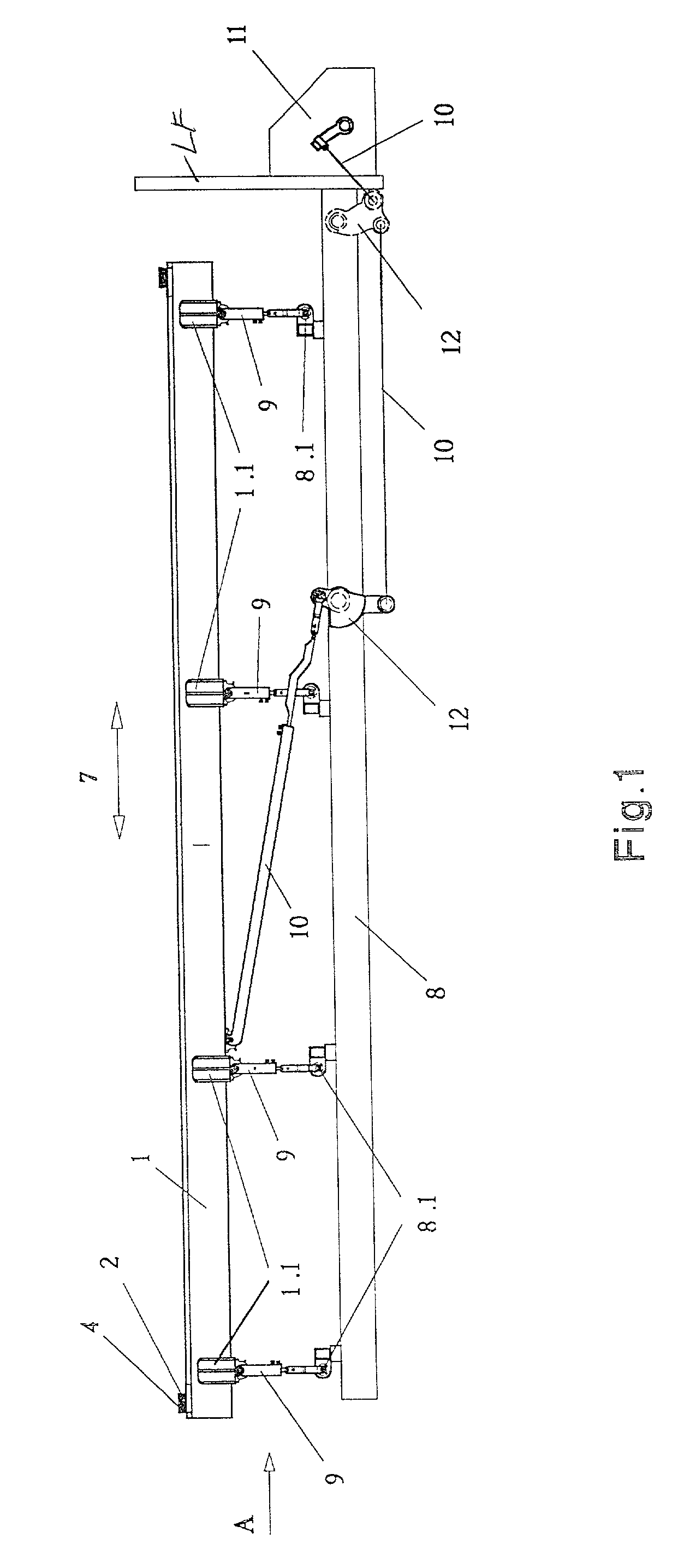
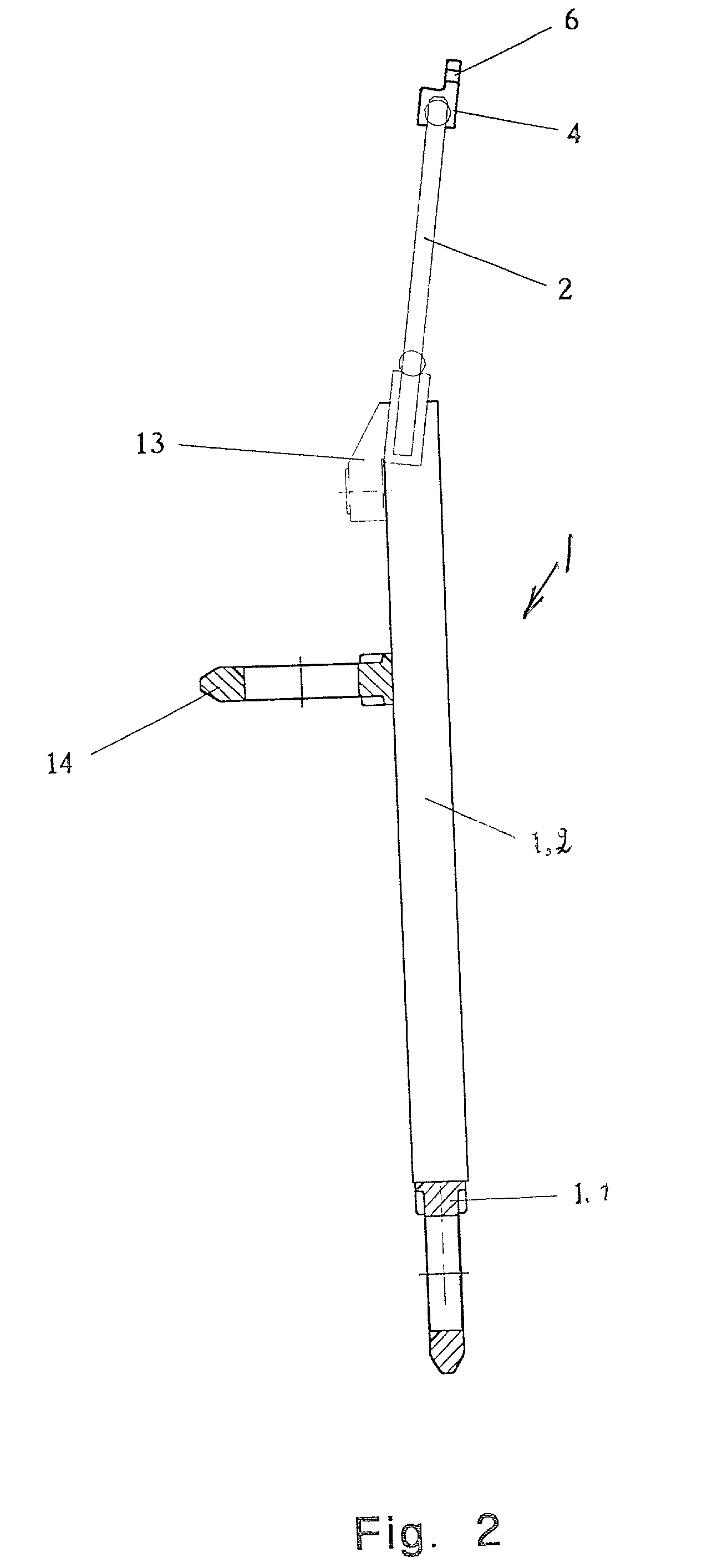
[0036] FIG. 1 shows the first embodiment according to the invention illustrating the first warp control section 1 constructed as a frame structure having a horizontal length extending over the weaving width of a loom. The first section 1 includes a guide member 2 for guiding the leno threads 3 and a guide bar 4 for guiding the ground threads 5 as seen in more detail in FIGS. 6 and 8. The guide element 2 comprises a reed type thread guide connected to the frame structure of the first warp control section 1. The guide bar 4 comprises a multitude of passages 6 extending axially and parallel relative to each other. One passage 6 is provided for each ground thread. The passages 6 may be optionally upwardly open or closed.

[0037] The first section 1 is connected to a drive 11 through a drive transmission to be described below for driving a horizontal oscillatory motion as indicated by the arrow 7. This motion is limited to a few millimeters which are adequate to properly guide the ground t...


PUM


Abstract

A warp thread control system for forming the loom shed as a first control section (1) and a second warp control section (16). The first section is equipped with at least one guide element (2) for guiding the leno threads (3) and a guide rod (4) carrying a multitude of passages 6 arranged and parallel to one another for guiding the ground threads (5). The second warp control section (16) includes a thread detour element (17) for detouring the leno threads (3) and a needle bar (18) carrying a multitude of needles (19) with needle eyes (19.1) for guiding the leno threads (3). Both the first warp control section (1) and the second warp control section (16) are positioned on the side of the reed facing the warp threads whereby the positioning may differ either above or below a weaving plane (28) or partially above and partially below the weaving plane (28). Preferably but not necessarily both warp control sections are driven by a common drive (11).

Description

PRIORITY CLAIM[0001] This application is based on and claims the priority under 35 U.S.C. .sctn.119 of German Patent Application 100 03 919.7, filed on Jan. 29, 2000, and 100 57 692.3, filed on Nov. 21, 2000, the entire disclosures of which are incorporated herein by reference.[0002] The invention relates to a weaving loom for the production of a leno fabric or cloth in which warp guide sections are provided for guiding the leno threads and the ground threads in the proper loom shed formation.BACKGROUND INFORMATION[0003] International Patent Publication WO 98 / 07913 discloses a device for controlling warp threads for the production of leno fabrics on a textile machine. Preferably the known device is part of a weaving loom and includes a sley carrying a conventional reed. A needle carrier carrying a multitude of needles is positioned above the fabric plane on the side of the reed facing the warps. The fabric plane is determined by the position of the beat-up line which extends in the ...

Claims


Application Information

Patent Timeline
Patent Type & Authority Applications(United States)
IPC IPC(8): D03D47/28D03C7/00D03C7/06D03D47/44
CPCD03C7/00D03C7/06
Inventor DORNIER, PETER D.WAHHOUD, ADNANKRUMM, VALENTINHAEUSSLER, HORSTVOSSEN, JUERGENHEHLE, JOSEF
Owner LINDAUER DORNIER GMBH
Why Eureka
Try Eureka