
Direct injection type internal combustion engine

a technology of internal combustion engine and injection type, which is applied in the direction of machines/engines, non-mechanical valves, electrical control, etc., can solve the problem of inability to carry out stratification operations

Inactive Publication Date: 2001-09-27
HITACHI LTD
View PDF0 Cites 19 Cited by
  • Summary
  • Abstract
  • Description
  • Claims
  • Application Information

AI Technical Summary

Benefits of technology

[0008] Another object of the present invention is to provide a direct injection type internal combustion engine wherein a discharge of an unburned fuel can be minimized.
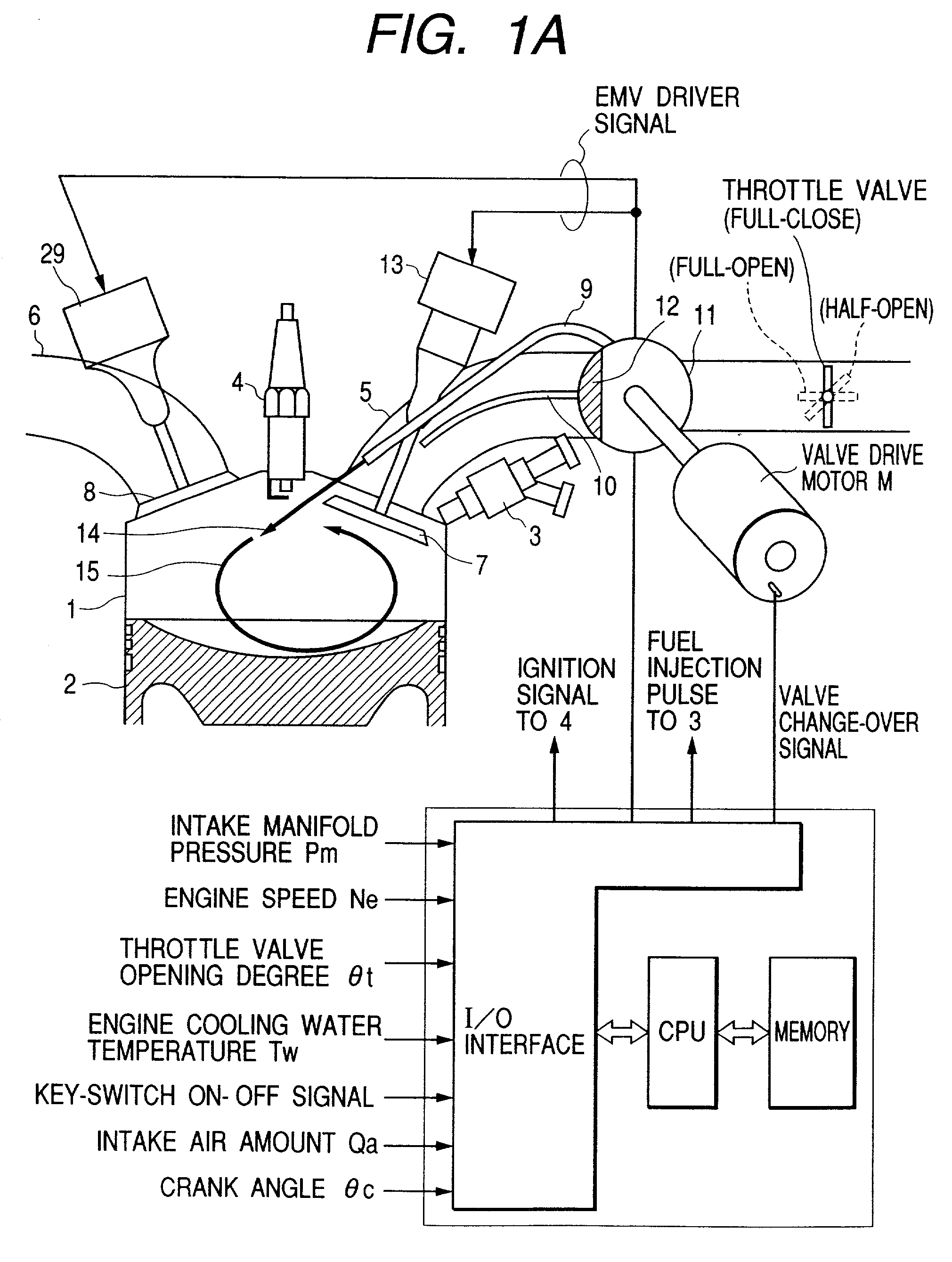
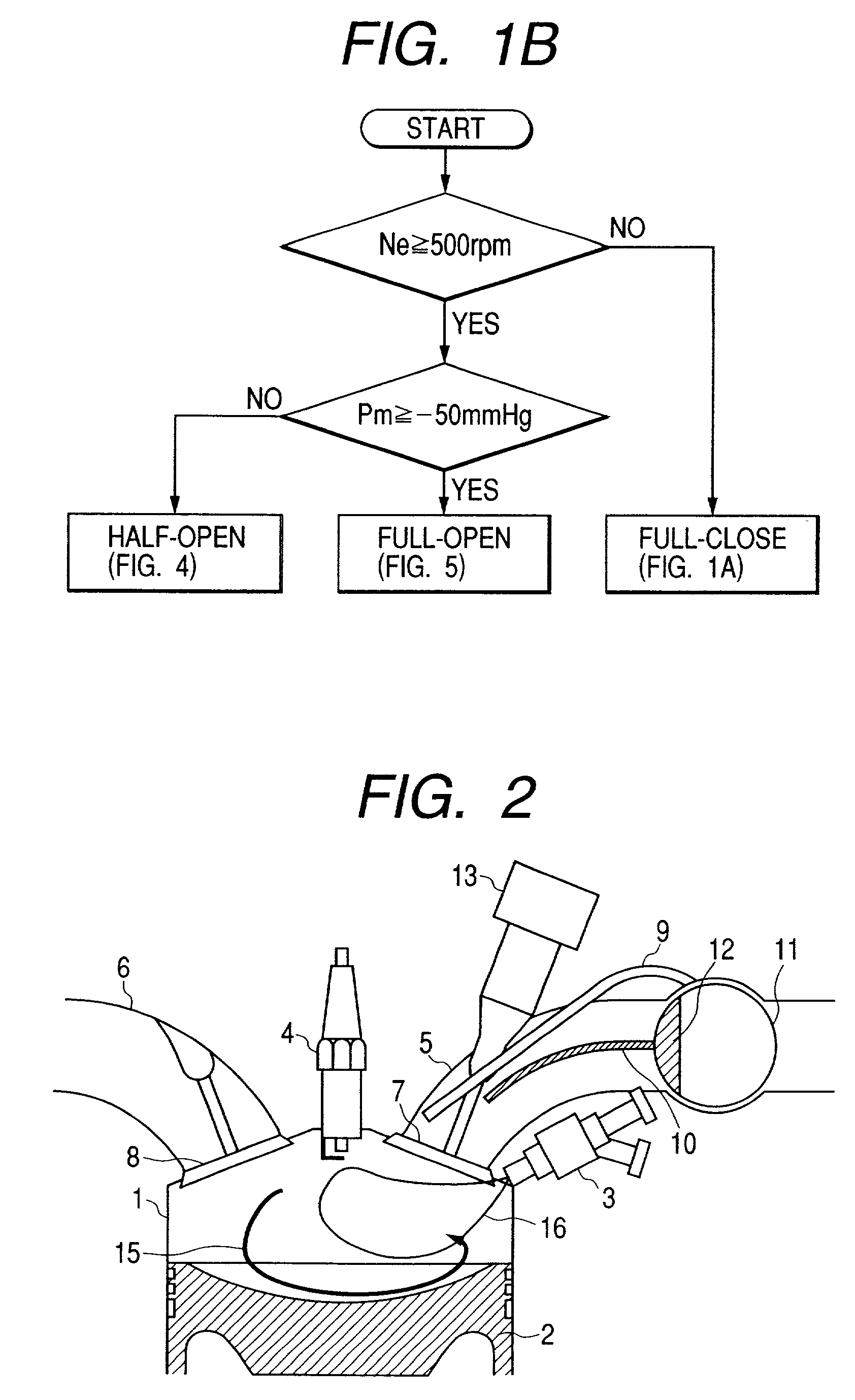
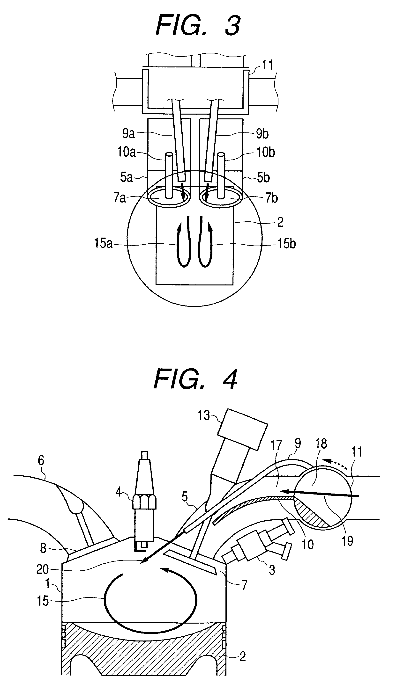
[0009] According to the present invention, in the starting time in which an air motion is small, means for heightening the motion of the air is added, from the starting time it is possible to carry out the stratification combustion operation, and the discharge of the unburned fuel is minimized.
[0017] According to the present invention, a direct injection type internal combustion engine comprises a fuel injector for injecting directly a fuel into a combustion chamber, an ignition coil for igniting an air-fuel mixture of the combustion chamber, and an air-fuel mixture induction device for forming an air-fuel mixture region which enable to easily spark at a vicinity of the ignition plug during a starting of the internal combustion engine.

Problems solved by technology

However, during a starting time of the engine, since a motion of the air in the cylinder is little, it is impossible to carry out a stratification operation.
In the case of the homogenous combustion, the fuel is supplied to a whole cylinder, in a case in which the engine is cooled comparatively, such as the starting time, there is many discharge of an unburned fuel and there is a problem on an exhaust air countermeasure.

Method used


Image

  • Direct injection type internal combustion engine
  • Direct injection type internal combustion engine
  • Direct injection type internal combustion engine

Examples


Embodiment Construction

[0001] 1. Technical Field

[0002] The present invention relates to a direct injection type internal combustion engine (hereinafter, an internal combustion engine is called as an "engine"), and in particularly to a technique for controlling a supply of air into a cylinder in a direct injection type combustion engine.

[0003] 2. Prior Art

[0004] In a conventional technique of a direct injection type internal combustion engine, for example, into a cylinder the fuel is injected directly and also the fuel having a rich air-fuel mixture is gathered in a vicinity of an ignition plug and burned, as a whole it is possible to carry out a stratification combustion for forming a lean (thin) air-fuel ratio combustion. However, during a starting time of the engine, since a motion of the air in the cylinder is little, it is impossible to carry out a stratification operation.

[0005] As shown in the engine according to the prior art, a homogenous combustion for forming an uniform air-fuel mixture is emplo...


PUM


Abstract

In a starting time in which an air motion is little, a means for heightening the motion is added, from the starting time a stratification combustion operation is enable to carry out, and a discharge of an unburned fuel is minimized. From the starting time of an engine (from the firstly combustion cylinder) it is possible to carry out a stable stratification combustion. In accordance with the stratification combustion in the exhaust air a large quantity of the surplus oxygen remains. In the engine in the exhaust stroke twice (two time) fuel injection is carried out and the after burn phenomenon is caused in the exhaust port and then the exhaust gas temperature can be raised.

Description

DESCRIPTION OF THE INVENTION[0001] 1. Technical Field[0002] The present invention relates to a direct injection type internal combustion engine (hereinafter, an internal combustion engine is called as an "engine"), and in particularly to a technique for controlling a supply of air into a cylinder in a direct injection type combustion engine.[0003] 2. Prior Art[0004] In a conventional technique of a direct injection type internal combustion engine, for example, into a cylinder the fuel is injected directly and also the fuel having a rich air-fuel mixture is gathered in a vicinity of an ignition plug and burned, as a whole it is possible to carry out a stratification combustion for forming a lean (thin) air-fuel ratio combustion. However, during a starting time of the engine, since a motion of the air in the cylinder is little, it is impossible to carry out a stratification operation.[0005] As shown in the engine according to the prior art, a homogenous combustion for forming an unifo...

Claims


Application Information

Patent Timeline
Patent Type & Authority Applications(United States)
IPC IPC(8): F01L3/06F01L7/02F01L9/04F02B17/00F02B23/10F02B31/00F02B31/06F02B75/12F02D13/02F02D41/06F02D41/30F02M69/00
CPCF02B17/005F02B31/06F02B2075/125F02B2275/48F02D41/062F02D41/3023F02F1/4242Y02T10/125Y02T10/146Y02T10/123Y02T10/12
Inventor FUJIEDA, MAMORUFUJII, HIROSHISHIRAISHI, TAKUYA
Owner HITACHI LTD
Learn More