Flat lamination solenoid

Inactive Publication Date: 2001-10-18
BERGSTROM GARY E +1
View PDF0 Cites 32 Cited by
  • Summary
  • Abstract
  • Description
  • Claims
  • Application Information

AI Technical Summary

Benefits of technology

0010] It is an object of the invention to provide a solenoid armature made of laminations, such that the planes of the laminations lie flat in a plane perpendicular to an axial direction of motion of the armature. Laminations in such an orientation will henceforth be described as "flat" or "lying flat", phrases intended here to indicate an orientation perpendicular to an axis of armature motion, rather than simply describing the laminations as planar. A further related object is to make a flat lamination armature strong, to resist bending moments associated with axial forces of electromagnetic attraction and of mass acceleration and of pole face impact. A still further object is to orient laminations so that they inhibit induced eddy currents. To supplement the effect of flat laminations and inhibit eddy currents induced within a flat armature lamination plane by axial c

Problems solved by technology

Even with silicon steels, however, eddy current losses present significant performance problems in two broad classes of solenoids.
Rapid energization and de-energization induces large eddy currents in unlaminated metal solenoids, with several adverse consequences.
First is the matter of heating and power dissipation, which become significant for solenoids that are operated very frequently.
Second is the dissipation-related issue of output capacity for the solenoid power supply and switching electronics--capacity that must be increased to overcome eddy current losses.
Third is the issue of response s

Method used


Image

  • Flat lamination solenoid
  • Flat lamination solenoid
  • Flat lamination solenoid

Examples


Embodiment Construction

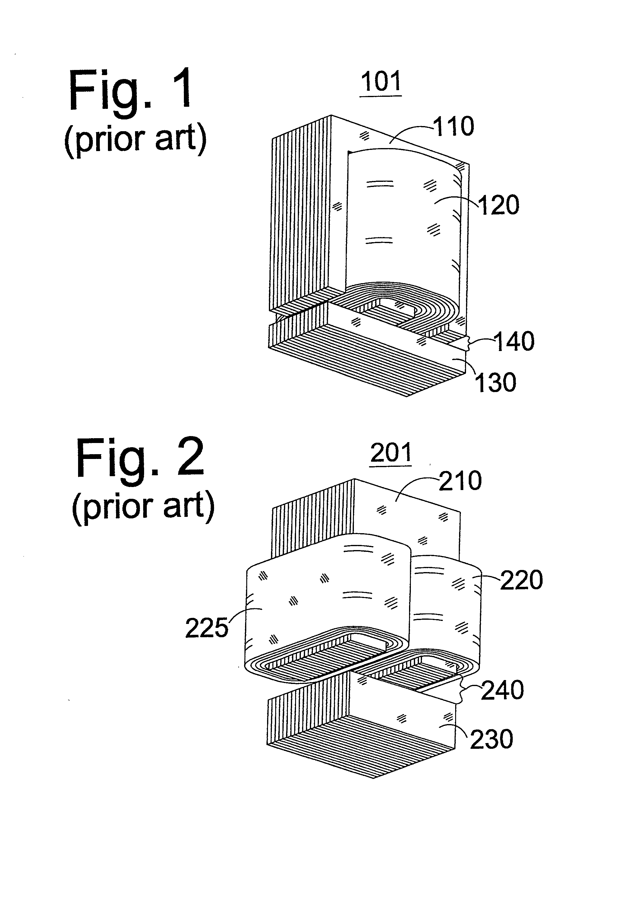
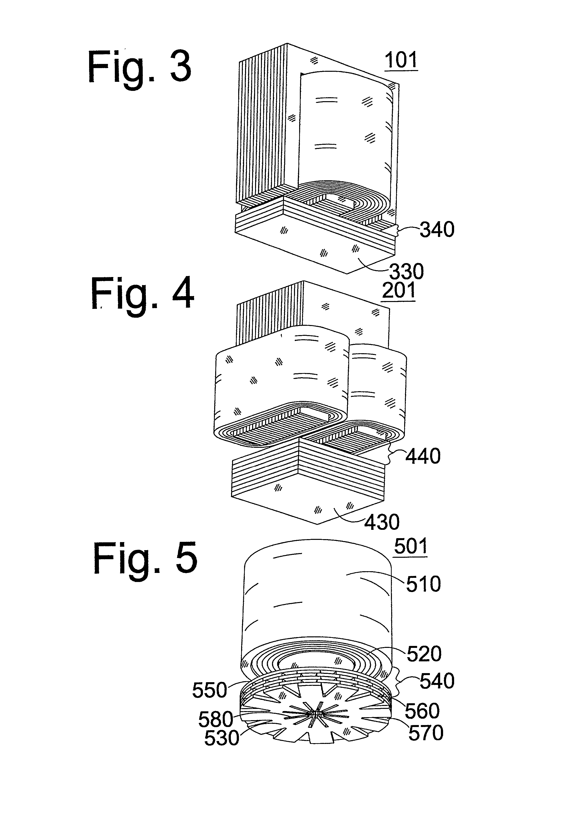
[0022] Starting from the prior-art "E-I" topology of FIG. 1, FIG. 3 shows the same stator structure 101, including the yoke and winding, along with a gap 340 analogous to gap 140 between the yoke and armature of FIG. 1. Armature 330 is seen to include laminations lying in a "flat" or horizontal plane, perpendicular to the axis of armature motion. If the laminations are joined by a strong adhesive, the armature becomes extremely rigid and strong. Mechanical connection to 330 might be accomplished by drilling through the middle and attaching a shaft through the armature. The many alternatives for mechanical connection are not discussed here, nor are they illustrated.

[0023] Starting similarly from the prior-art "U-I" topology of FIG. 2, FIG. 4 shows the same stator structure 201, including the yoke and windings, along with a gap 440 analogous to gap 240. Like 330, armature 430 is seen to include laminations that are "flat," i.e. lying in a plane perpendicular to the axis of armature mo...


PUM


Abstract

A variable reluctance solenoid includes an armature and a yoke located axially beyond one end of the armature. Magnetic attraction across an axial gap between the armature and yoke causes the armature to move axially and close the gap. The armature includes ferromagnetic laminations lying in a plane perpendicular to the axial direction. These laminations may include slots, proportioned and directed to combat eddy currents and reduce moving mass while avoiding creation of flux bottlenecks. The solenoid may have two yokes on opposite sides of the armature, providing reciprocating armature motion.

Description

[0001] This application claims the priority benefit of U.S. provisional patent application Ser. No. 60 / 171,326, of the same title and naming Gary Bergstrom as inventor.[0002] This invention relates to solenoids using ferromagnetic armatures subdivided into laminations to reduce eddy current losses. It relates more specifically to a lamination stacking geometry that combines good electrical / magnetic properties with high mechanical strength. It further relates to the use of stacks of slotted laminations, to provide an armature with high strength, reduced weight, high flux handling, and low eddy current losses. This invention is applicable especially to actuation solenoids for automotive engine valves.[0003] Most solenoids are fabricated from iron or silicon steel alloys, where silicon alloying causes a large increase in electrical resistivity, which is traded off against a small decrease in flux handling capacity. Even with silicon steels, however, eddy current losses present signific...

Claims


Application Information

Patent Timeline
IPC IPC(8): H01F7/08H01F7/16
CPCH01F7/081H01F7/1638H01F2007/1676
Inventor BERGSTROM, GARY E.SEALE, JOSEPH B.
Owner BERGSTROM GARY E
Why Eureka
Try Eureka