
Substrate for optical recording media, optical recording medium, manufacturing process for optical recording media, and optical recording/reproducing method

Inactive Publication Date: 2001-10-18
SONY CORP
View PDF8 Cites 11 Cited by
  • Summary
  • Abstract
  • Description
  • Claims
  • Application Information

AI Technical Summary

Problems solved by technology

However, when the cycle of creating a groove is shortened, recording or reproducing becomes more susceptible to thermal interference such as thermal crosstalk, cross-writing, or cross-erasure occurring between adjoining tracks, that is, a groove and an adjoining land.
Consequently, a record signal may be undesirably erased or vanished, and a reproduced signal may be deteriorated or faded away.
This hinders realization of a high recording density.
Besides, the deposition of the layer on the sidewall diminishes the number of sputtered particles reaching the concave part.
This leads to a difference in sensitivity between a groove and an adjoining land and causes inhomogeneity of an optical disk.
This results in a high recording density.
When the wavelength thereof is 660 nm or more, it is hard to improve a recording density.
This becomes an obstacle to dies cutting or formation of the recording layer.
This leads to non-uniformity in thermal sensitivity.
This means that a domain wall is displaced properly in the concave part but improperly in the convex part.

Method used


Image

  • Substrate for optical recording media, optical recording medium, manufacturing process for optical recording media, and optical recording/reproducing method
  • Substrate for optical recording media, optical recording medium, manufacturing process for optical recording media, and optical recording/reproducing method
  • Substrate for optical recording media, optical recording medium, manufacturing process for optical recording media, and optical recording/reproducing method

Examples


first example

FOR COMPARISON

[0114] The substrate 11 for optical recording media is, as seen from the schematic sectional view of FIG. 7, analogous to the substrate 11 shown in FIG. 9. The substrate 11 of the present example for comparison is identical to that of the first example except that the border sidewall linking the concave part 2 and convex part 3 has a single sidewall plane. In FIG. 7, the same reference numerals are assigned to members identical to those shown in FIG. 5, and the description of the members will be omitted. Incidentally, an angle at which the sidewall meets the bed is 113.degree..

[0115] Even in the present example for comparison, the width of the concave parts 2 of the recording layer 5 and that of the convex parts 3 thereof are nearly equal to each other.

[0116] Even in this case, the discontinuous part 6 serving as a discontinuity of a layer is produced. The heat capacity, that is, volume of the recording layer observed on the apical plane of the convex part 3 is approxi...


PUM


Abstract

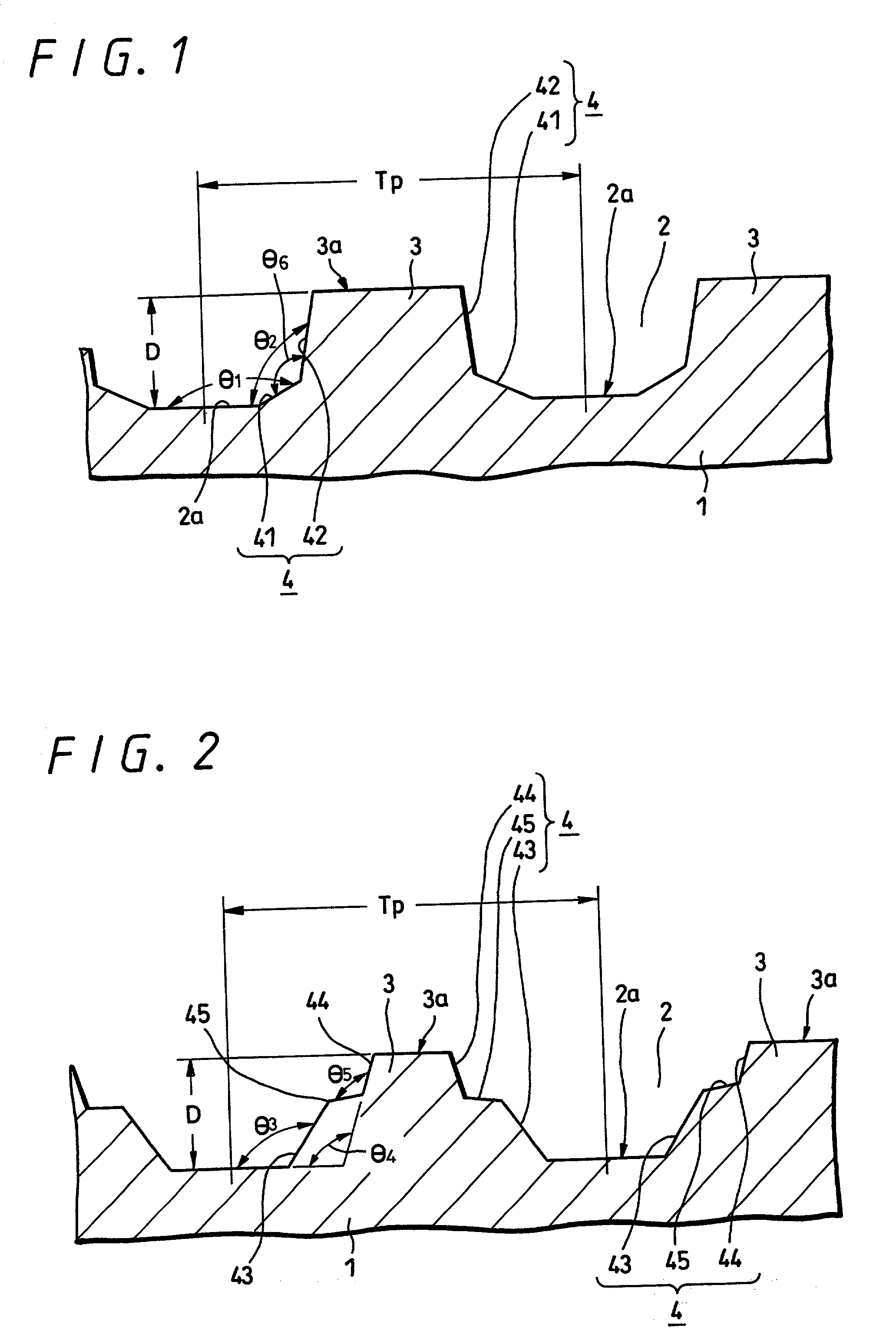
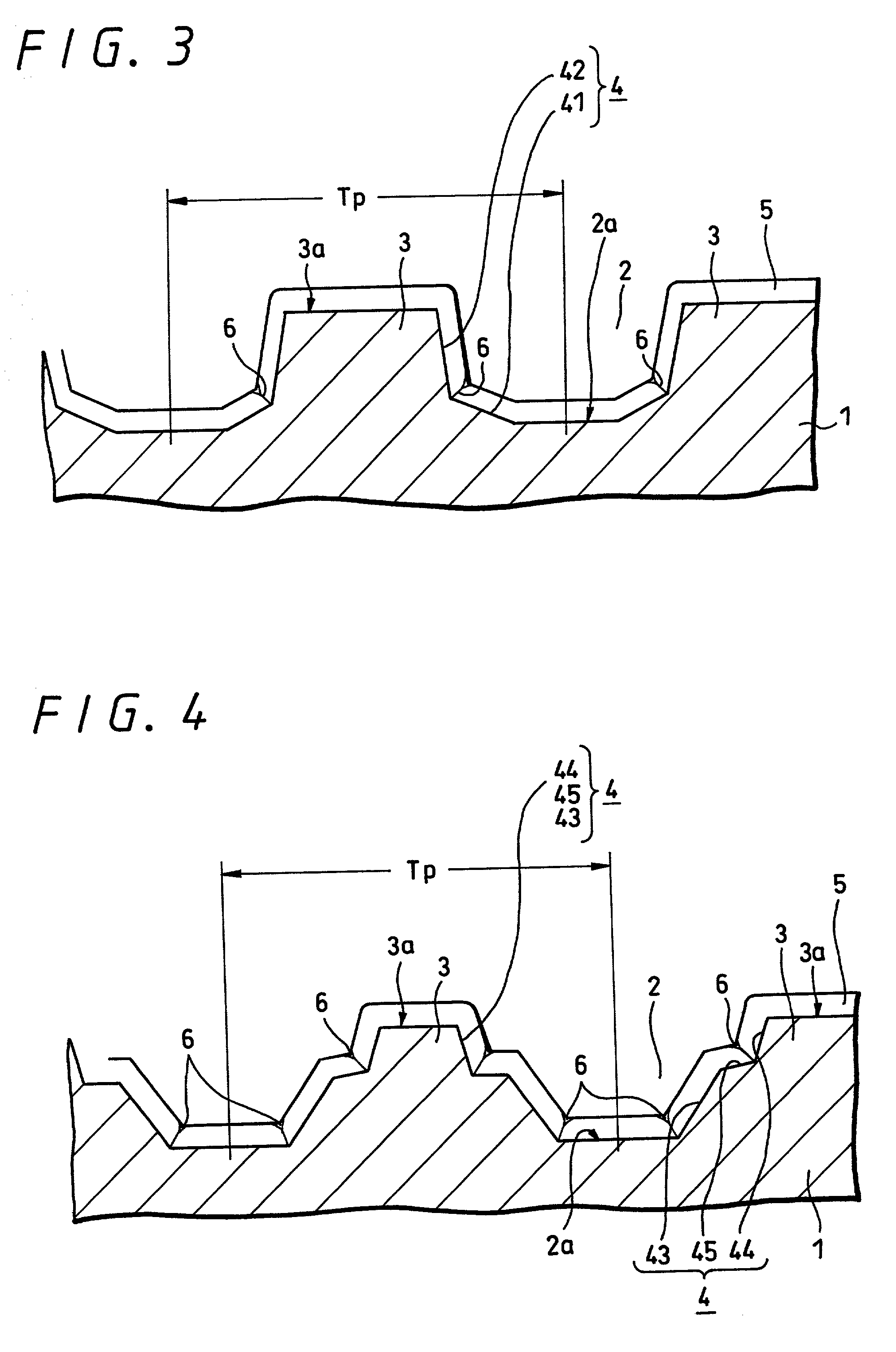
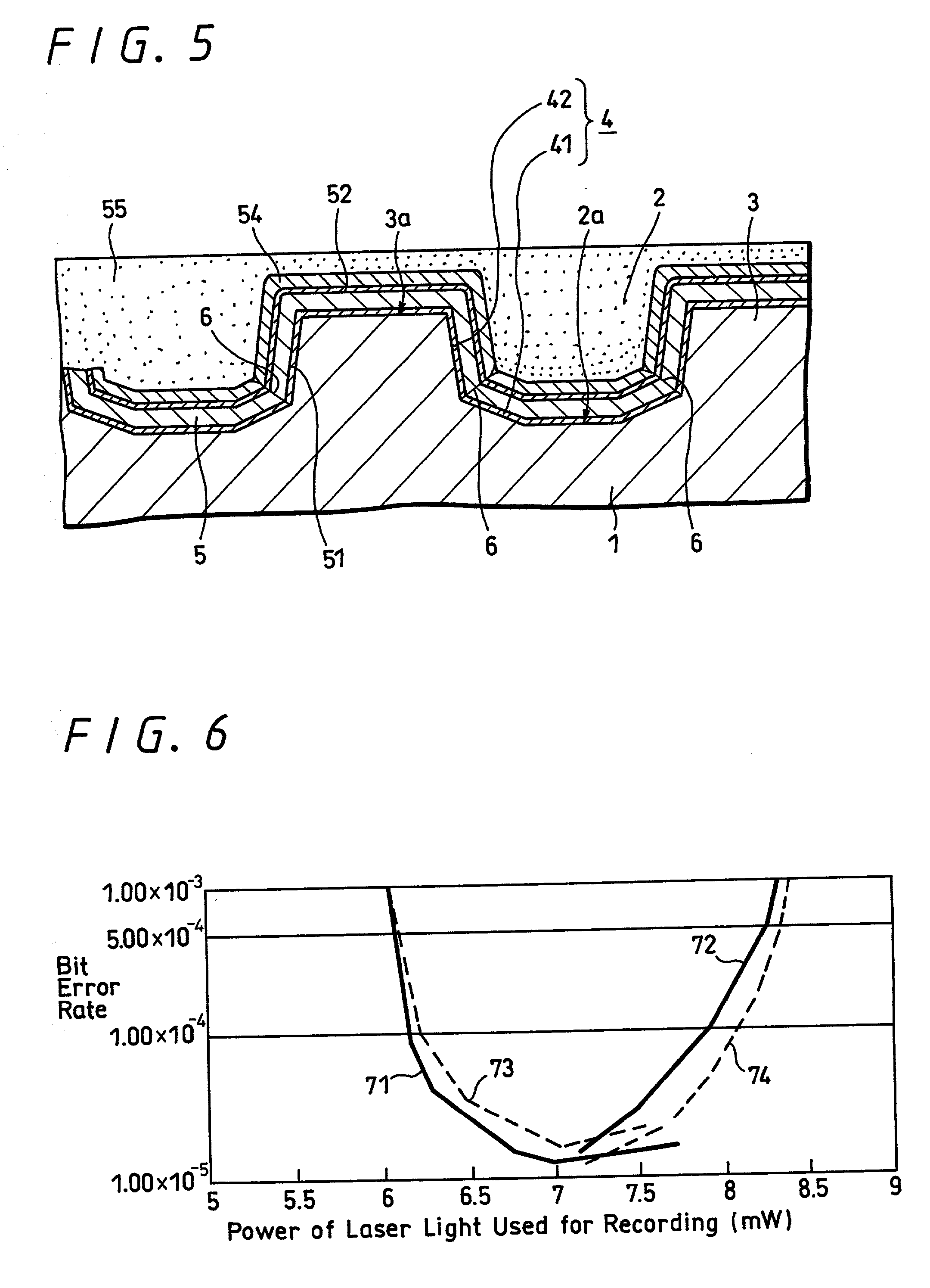
According to the present invention, when a land-groove recording method is adopted, thermal crosstalk between a land and an adjoining groove is suppressed effectively. Inhomogeneity of a recording layer between the land and groove is suppressed effectively. A substrate for optical recording media comprises groove-like concave parts (2) and convex parts each created between adjoining concave parts. A border sidewall (4) between a concave part and an adjoining convex part (2) has a plurality of sidewall planes, that is, at least a first sidewall plane (41) that leads to the bed of the concave part and a second sidewall plane (42) that leads to the apical plane of the convex part. The first sidewall plane meets the bed of the concave part at an angle ranging from 120° to less than 180°. The second sidewall plane meets the bed of the concave part at an angle ranging from 90° to 110°. A discontinuous part (6) is produced at least along a borderline between the first sidewall plane and second sidewall plane. The presence of the discontinuous part (6) is effective in minimizing thermal crosstalk between the concave part (2) and convex part (3) and suppressing inhomogeneity of a recording layer between a land and an adjoining groove.

Description

[0001] 1. Field of the Invention[0002] The present invention relates to a substrate for optical recording media of a so-called land-groove recording type, an optical recording medium, a manufacturing process for optical recording media, and an optical recording / reproducing method. More particularly, this invention is intended to minimize thermal crosstalk between adjoining tracks, that is, between a land and an adjoining groove, minimize a noise, and thus improve a recording density.[0003] 2. Description of the Related Art[0004] With the recent trend to digitization of information, there is an increasing demand for media in which a large amount of digital data can be recorded. Media capable of meeting the demand include a so-called phase change optical recording medium, for example, a phase change optical disk, and a magnetooptical disk. The phase change optical recording medium has crystallinity thereof thermally changed to change the optical characteristic thereof, whereby recordi...

Claims


Application Information

Patent Timeline
IPC IPC(8): G11B7/004G11B7/007G11B7/2405G11B7/24073G11B7/24076G11B7/24079G11B7/24085G11B7/24091G11B7/253G11B7/26G11B11/105
CPCG11B7/00718G11B7/24076G11B7/253G11B7/2531G11B7/2534G11B7/26G11B11/10578G11B11/10584G11B2007/24304
Inventor SAKAMOTO, TETSUHIROFUJITA, GORO
Owner SONY CORP
Learn More