Suspension system for motor vehicles

a suspension system and motor vehicle technology, applied in the direction of shock absorbers, mechanical equipment, transportation and packaging, etc., can solve the problems of inability to retrofit suspension units of this type into existing vehicles, constant monitoring of the medium, and need for hydraulic lines for forward and revers

Inactive Publication Date: 2001-10-25
ZF FRIEDRICHSHAFEN AG
View PDF0 Cites 45 Cited by
  • Summary
  • Abstract
  • Description
  • Claims
  • Application Information

AI Technical Summary

Problems solved by technology

A disadvantage in a suspension unit of this type is that the hydraulic lines are needed for the forward and reverse flow and the pressureless oil reservoirs require main

Method used


Image

  • Suspension system for motor vehicles

Examples


Embodiment Construction

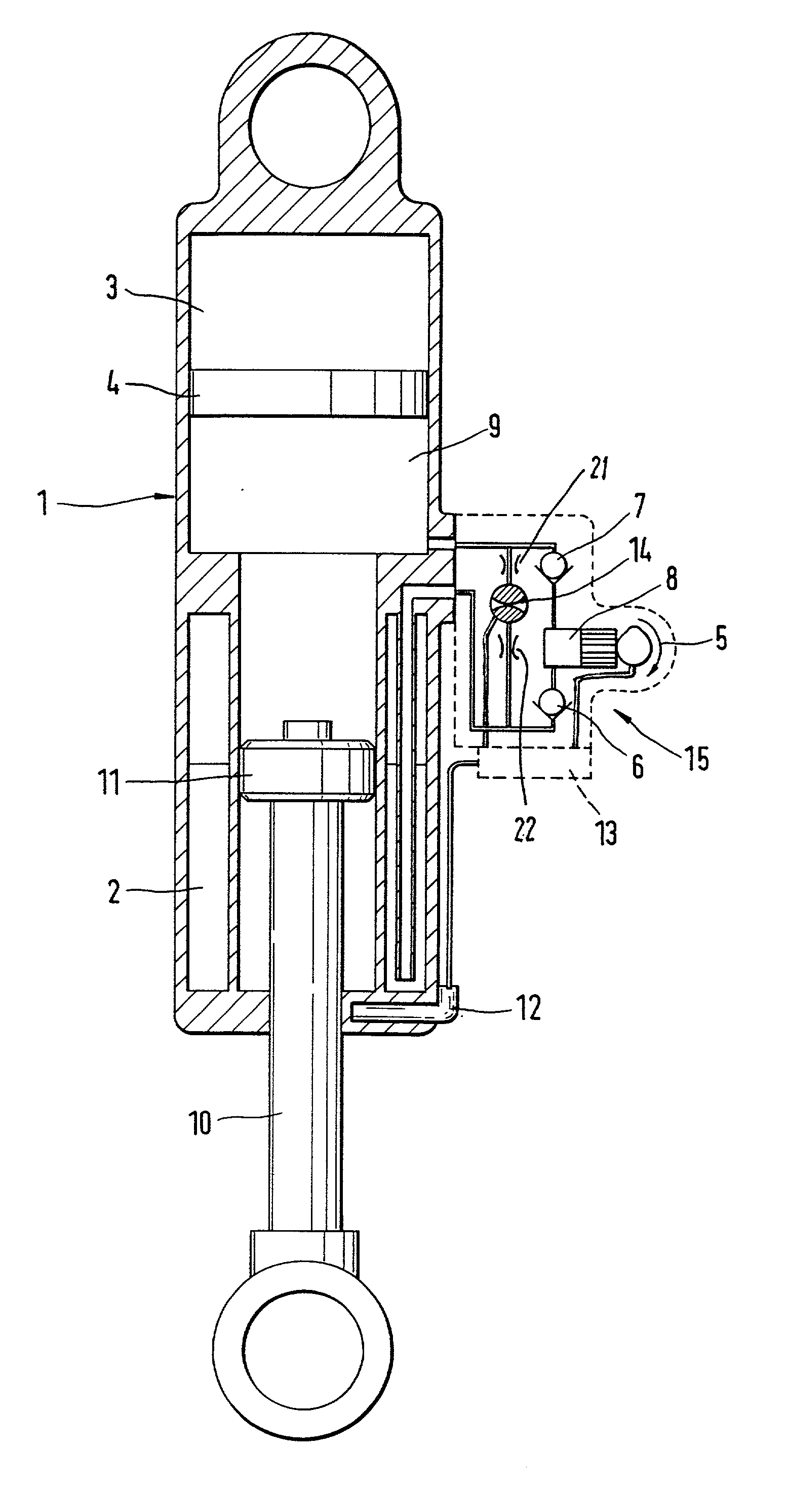
[0015] FIG. 1 shows a piston-cylinder unit 1 according to an embodiment of the present invention in which an oil reservoir 2 and a pneumatic or gas spring volume 3 are integrated. Oil and gas are separated in the gas spring volume 3 by a separating element 4. A pump 15 is arranged between the oil reservoir 2 and a high pressure area of the piston-cylinder unit 1. When a drive unit 5 of the pump 15 is switched on, a pump piston is set in axial movement by the rotating movement of a cam connected to the drive unit 5. A restoring force is exerted on the pump piston via a spring.

[0016] The pump piston draws oil from the oil reservoir 2 to a pump space 8 and delivers the oil from the pump space 8 to a high-pressure area 9 of the piston-cylinder unit 1 via an inlet valve 6 and an outlet valve 7. The gas spring volume 3 is gradually compressed and accordingly acts on the end face of the piston rod 10 during operation of the drive unit 5. As long as the drive unit 5 is operating, the piston...


PUM


Abstract

A suspension system for motor vehicles with level regulation for adjusting a predetermined height of the vehicle body includes at least one piston-cylinder unit with a work cylinder, a piston rod and a damping piston having damping valves. A pump is connected between an oil reservoir and the piston cylinder unit via corresponding inlet and outlet lines. The pump is driven by a drive unit and the level height is detected by a sensor which acts on the drive unit or on a regulating valve via evaluating electronics.

Description

[0001] 1. Field of the Invention[0002] The present invention relates to a suspension system for motor vehicles with level regulation for adjusting a predetermined height of the vehicle body including at least one piston-cylinder unit having a work cylinder, a piston rod and a damping piston with damping valves, and a pump for an oil reservoir and corresponding inlet and outlet lines between the oil reservoir and the piston-cylinder unit.[0003] 2. Description of the Related Art[0004] Suspensions with automatic level regulation for motor vehicles are already known, for example, from German reference DE 32 12 433 A1 in which the suspension units of the vehicle wheels are supplied from a central oil reservoir via correspondingly open hydraulic lines. Actuating valves are required for connecting the suspension units with the oil reservoir and are supplied with an appropriate amount of oil from the oil reservoir by a central pump. A flow regulator and a height sensor act in the oil circui...

Claims


Application Information

Patent Timeline
IPC IPC(8): B60G17/044F16F9/06B60G17/08F16F9/32F16F9/34F16F9/50
CPCB60G2202/154B60G2202/416B60G2400/252B60G2500/112B60G2500/206B60G2500/30B60G2800/912B60G2800/914F16F9/064
Inventor BECK, HUBERTEULENBACH, DIETER
Owner ZF FRIEDRICHSHAFEN AG
Why Eureka
Try Eureka