Stone cutter

Inactive Publication Date: 2001-11-01
ONEAL ROY G +2
View PDF0 Cites 2 Cited by
  • Summary
  • Abstract
  • Description
  • Claims
  • Application Information

AI Technical Summary

Benefits of technology

[0009] The force is sufficient to break the stone. The invention may operate slowly in order to not shatter the stones requiring a steady break.
[0012] It is therefore an object of the invention to provide a stone cutter which can be easily used and which is very mobile which can be utilized in order to cut stone or brick of various types and having irregular shapes.

Problems solved by technology

In the art of stone cutting most stones are cut by hand and it is a long and tedious process.
It involves the use of laborious techniques with hand held metal tools, table mounted saws and scoring devices.

Method used


Image

  • Stone cutter
  • Stone cutter

Examples


Embodiment Construction

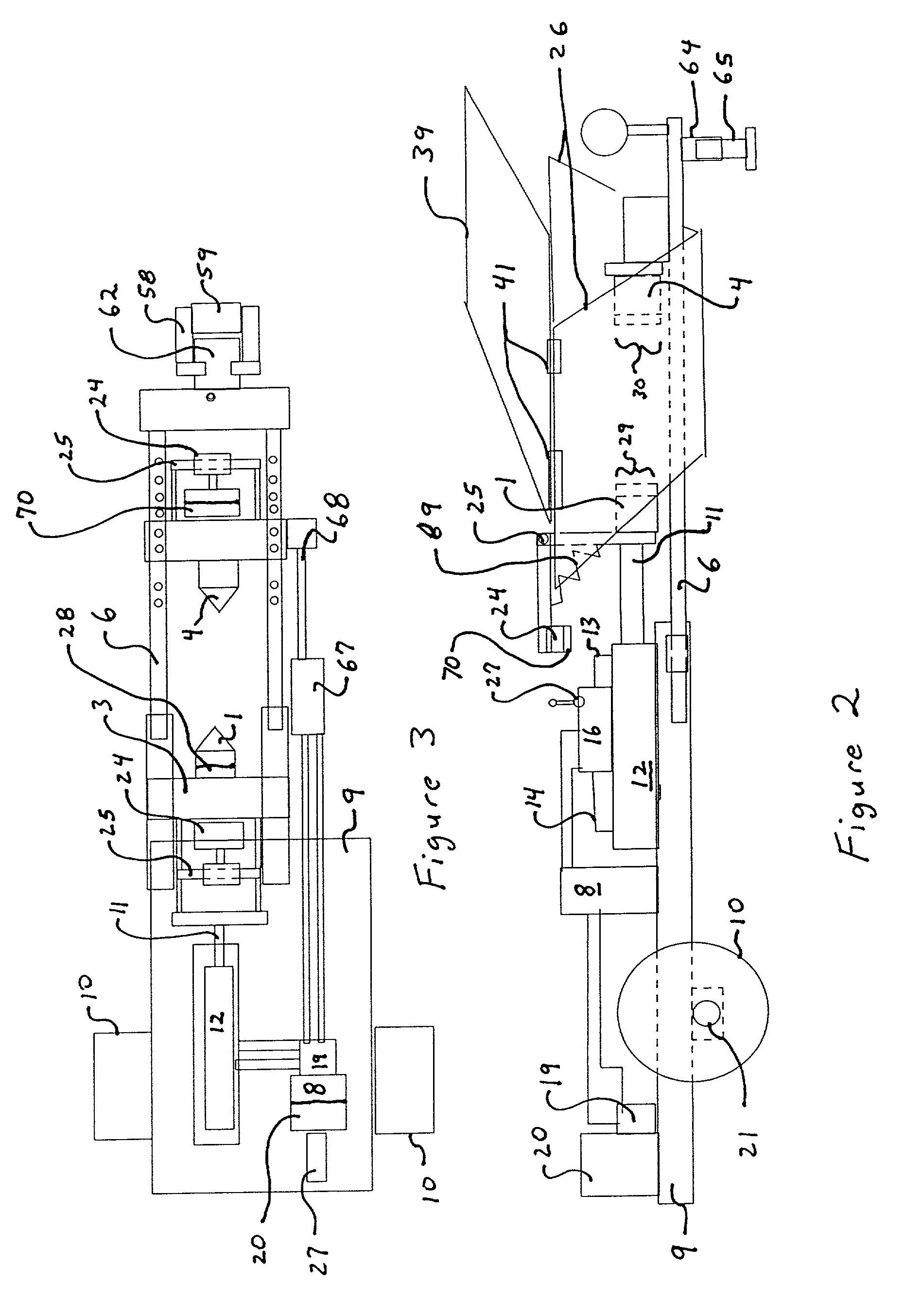
[0018] Two separate side views of two separate embodiments are shown in the drawings.

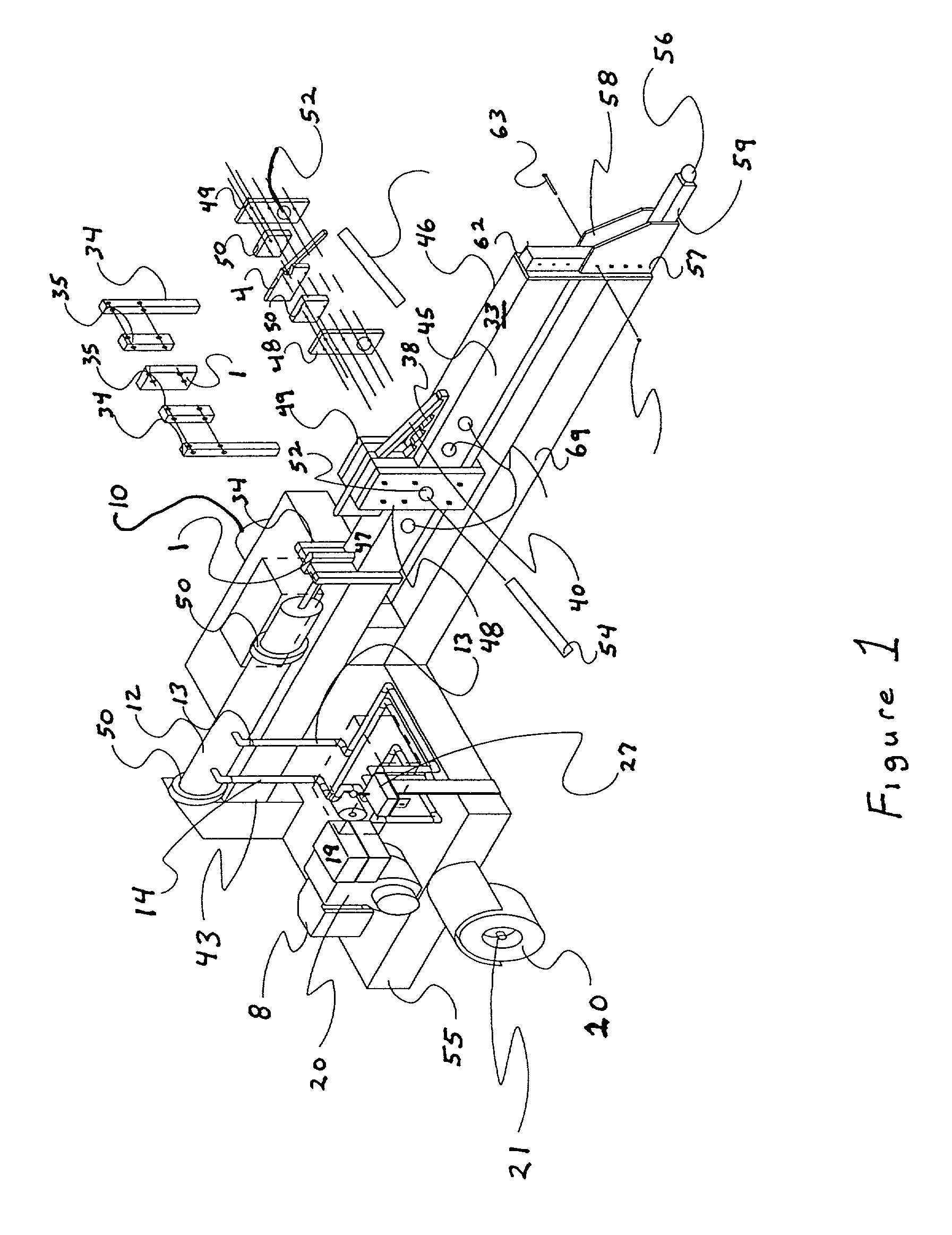
[0019] Referring to FIG. 1 the rock cutter for splitting stones has (a) a support means, iron bar 42, having a first end 43, a second end 44, a left side 45 and a right side 46 and a support length between the first end and the second end and a support surface 47 along the support length for supporting a rock to be cut (not shown). A lower

[0020] The first blade holding means is defined by a support arm 48 slidably contacting the left side and a support arm 49 slidably contacting the right side of the iron bar 42 so that the position of the first blade 1, held centered by centering spacers 50 is supported slightly above (by the spacers 50) and on either side (by the support arms 48 and 49) of the iron bar 42 as the blade 1 moves along the support length. If necessary, the bottom of the two support arms may be attached for added support. The piston is also supported by two rings 51 so that the piston ...


PUM

PropertyMeasurementUnit
Lengthaaaaaaaaaa
Forceaaaaaaaaaa
Angleaaaaaaaaaa

Abstract

A rock cutter for splitting stones is disclosed which shows a support surface for holding the rock and (a) a first blade and (b) a second blade which may be position to hold the rock between the first and second blades and on the support surface along with a means for moving the first blade towards the second blade. The means for moving comprises a hydraulicly driven piston having a piston arm to which the first blade is mounted. The invention also includes shock means for applying a sudden force to the first blade. The rock cutter also has a cover which is used in conjunction with a means for receiving pieces at an angle after the split.

Description

[0001] PRIORITY[0002] This patent is a continuation of Provisional Patent: No. 60 / 202,498 filed May 5, 2000.[0003] The present invention relates to stone cutting and more particularly it is a stone cutter using a hydraulically driven wedge in order break stones.PRIOR ART[0004] In the art of stone cutting most stones are cut by hand and it is a long and tedious process.[0005] It involves the use of laborious techniques with hand held metal tools, table mounted saws and scoring devices.GENERAL DISCUSSION OF THE INVENTION[0006] The invention is a stone splitter which utilizes a hydraulic arm ending in a point or wedge in order to split stones. The hydraulic arm has a point on one end and the opposite end fits within a hydraulic cylinder which forces the wedge into the stone. A fixed wedge opposite the wedge on the hydraulic arm is provided.[0007] A power supply provides for hydraulic fluid under pressure as with an electric pump or gas pump.[0008] In order to get an adequate result, th...

Claims


Application Information

Patent Timeline
IPC IPC(8): B28D1/22B28D1/26
CPCB28D1/222B28D1/26
Inventor O'NEAL, ROY G.TREADAWAY, FRANKSWAFFORD, RONALD E.
Owner ONEAL ROY G
Why Eureka
Try Eureka