
Gas burner

Inactive Publication Date: 2001-11-01
BRAY BURNERS
View PDF0 Cites 32 Cited by
  • Summary
  • Abstract
  • Description
  • Claims
  • Application Information

AI Technical Summary

Benefits of technology

[0010] It is an object of the invention to provide a burner which is inexpensive and simple to construct and which nevertheless provides sufficient heat radiation downwardly of its surface when disposed above a food product to cook same when in use as a grill.
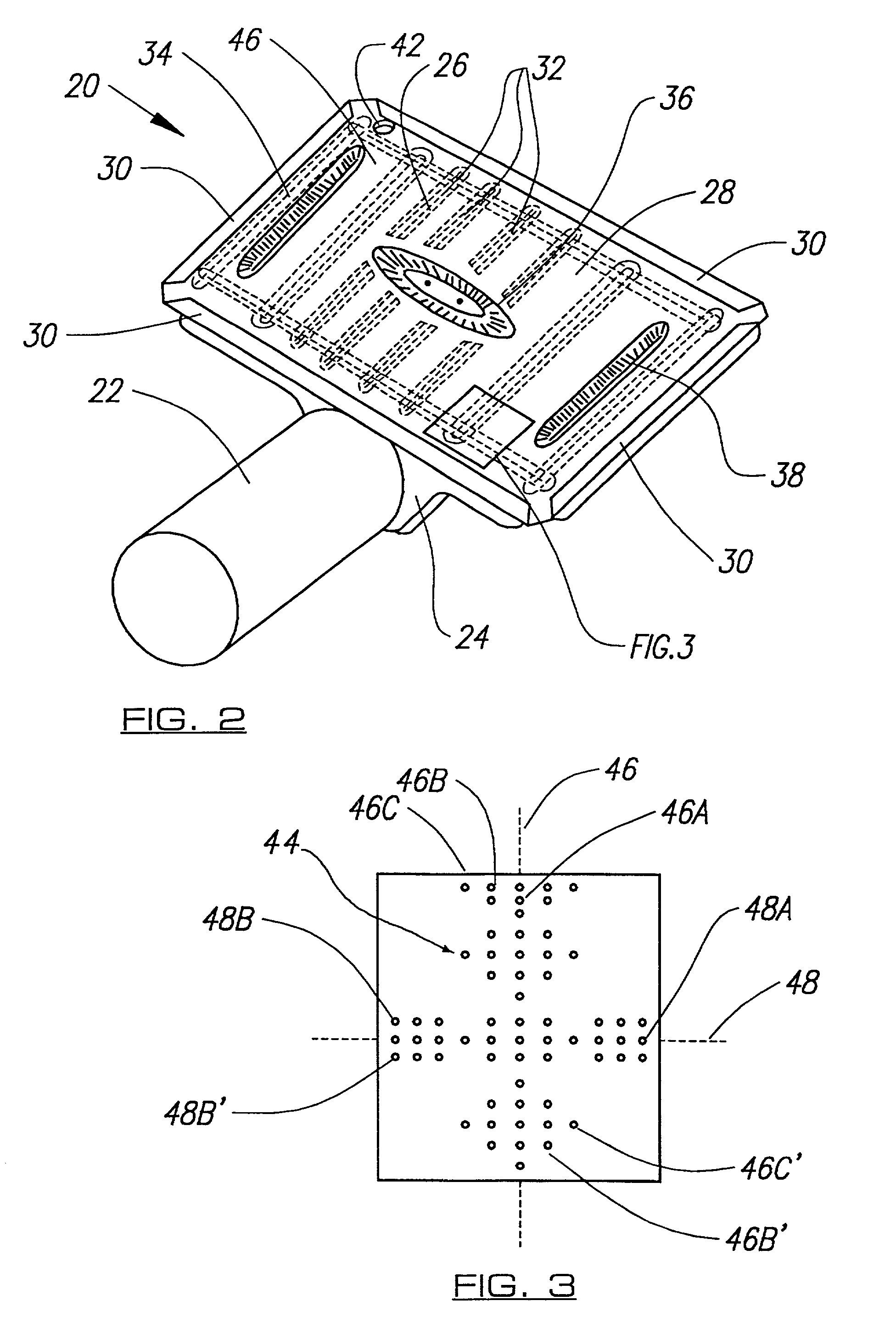
[0011] According to the invention there is provided a burner head having an inlet port by which the burner is provided with a combustible gas, a chamber in which the combustion gas flows prior to combustion, and a combustion surface through which the gas passes from the chamber to combust thereon or proximate thereto, characterized in that the combustion surface is provided with a pattern of perforations, the total area of perforation as compared to the area of the combustion surface being sufficient to permit a sufficient quantity of gas to flow therethrough, and each perforation being of size which prevents any burn back within the chamber.
[0013] The removal of the sheets of gauze from the construction of the burner has never previously been considered because of the requirement of heat radiation therefrom. The applicant has established that by simply providing a perforated combustion surface through which the combustion gas passes directly from the chamber, sufficient radiation of heat from the said combustion surface can be achieved without any requirement for portions of the combustion surface to glow.
[0015] Preferably the pattern of perforations within the sheet creates a substantially uniform flame profile on or proximate the surface thereof.
[0016] Preferably the combustion surface is provided with indentations to prevent significant buckling of the said surface during combustion thereon.

Problems solved by technology

The removal of the sheets of gauze from the construction of the burner has never previously been considered because of the requirement of heat radiation therefrom.

Method used


Image

  • Gas burner
  • Gas burner

Examples


Embodiment Construction

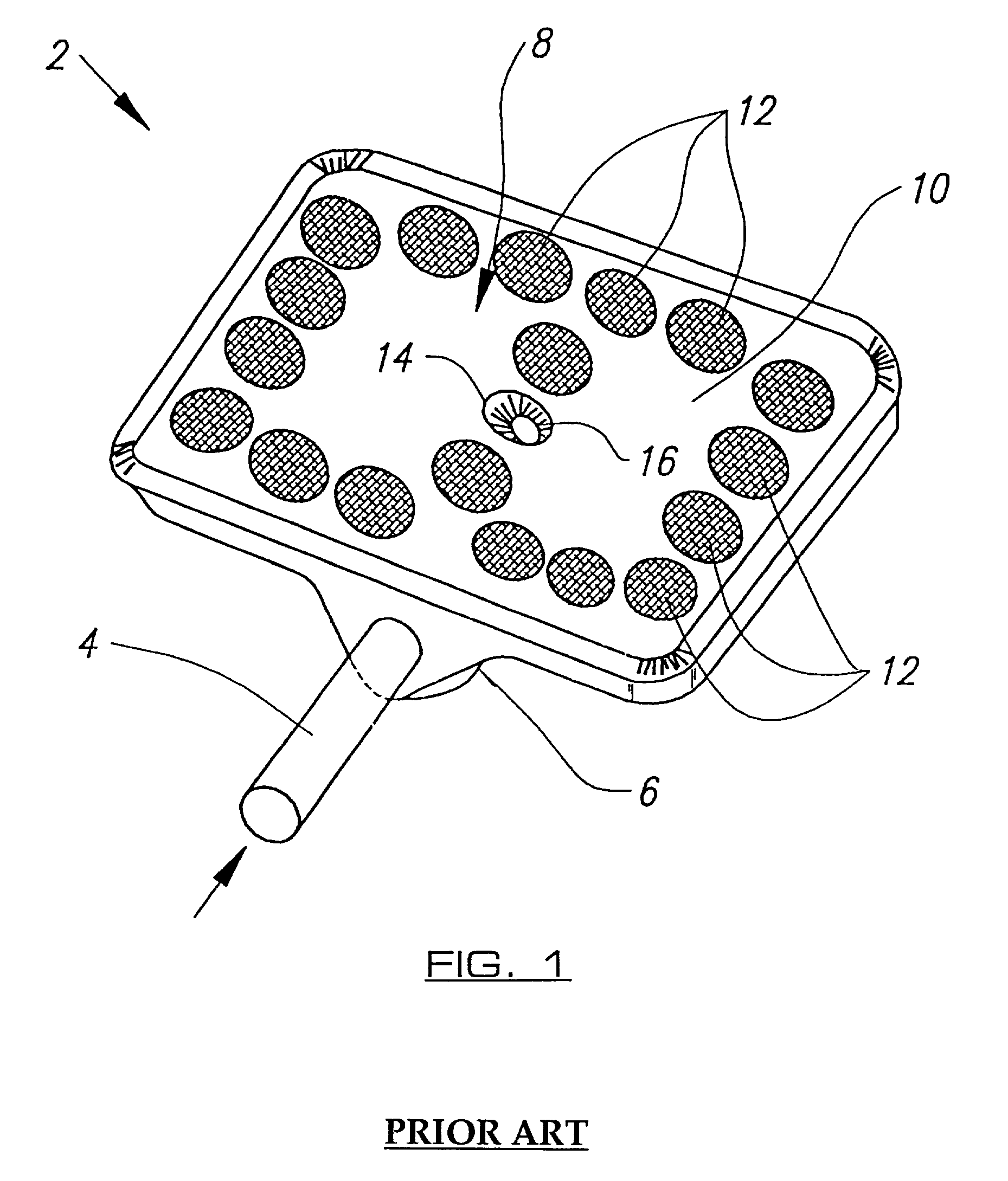
[0026] Referring firstly to FIG. 1 there is shown a burner head 2 of prior art configuration comprising a gas feed tube 4 which passes into a chamber 6 disposed underneath a combustion surface indicated generally by reference numeral 8. It should be pointed out that the burner heads shown in both FIGS. 1 and 2 are conventionally rotated through 180.degree. about the axis of the feed tube so that the combustion surface faces downwardly and the combustion which occurs thereon provides a grilling effect on products beneath the said burner head.

[0027] The combustion surface 8 is comprised of a punched template 10 which overlays two separate sheets of gauze arranged perpendicularly to one another to create a sufficient resistance to the flow of gas from within the chamber 6 through said sheets of gauze in the regions of apertures 12 provided in the punched template 10.

[0028] The combustion of the gas approximate or on the combustion surface 8 heats both the template 10 and the portions o...


PUM


Abstract

A radiative heat gas burner is described of the type which may be used to fire a domestic grill. The burner head has an inlet port and comprises a pressing which together with a perforated metal sheet defines a chamber in which a combustion gas flows prior to flowing through the perforations in the sheet and combusting thereon. The sheet of metal sealingly connected to the pressing forms a combustion surface on which the combustion of gas flowing through the perforations occurs, but the invention lies in the discovery that it is not necessary to provide large apertures in the sheet which reveal portions of gauze sheets disposed parallely behind the combustion surface and which glow and thus radiate heat during operation of the burner. It is merely necessary to provide a pattern of small perforations over the entire surface of the combustion sheet, the number of said perforations being sufficient to allow for sufficient gas flow therethrough to support stable combustion, and their pattern being ideally in rows which intersect with other rows in a substantially perpendicular manner.

Description

[0001] The following invention relates generally to a gas burner, and more specifically to a radiative heat gas burner of the type which are commonly incorporated in conventional gas cookers in the grills thereof.[0002] The type of burners to which this invention relates are also known as atmospheric burners because combustion occurs on the surface of the burner with oxygen from the ambient atmosphere fueling the combustion, but it to be understood that the invention may have wider application, in particular to premix burners in which air is mixed with assistance from a fan to a certain extent with the combustion gas prior to combustion thereof. In the interests of brevity however, the following description relates only to atmospheric burners.[0003] Atmospheric burners are used to provide the grill in conventional gas cookers. One configuration of burner typically consists of a plenum chamber fabricated by pressing a steel or aluminum sheet to form a cavity with an inlet port to whi...

Claims


Application Information

Patent Timeline
IPC IPC(8): F23D14/14
CPCF23D14/14F23D2203/102F23D2212/20F23D14/145
Inventor WOOD, GRAHAM
Owner BRAY BURNERS
Learn More