Aerodynamic noise reducing structure for aircraft wing slats

a technology of aerodynamic noise reduction and wing slats, which is applied in the direction of airflow influencers, transportation and packaging, efficient propulsion technologies, etc., can solve the problems of aerodynamic noise generated, becoming an evermore significant portion of the total flight noise, and aero-acoustic noise generated

Inactive Publication Date: 2001-11-08
AIRBUS OPERATIONS GMBH
View PDF0 Cites 43 Cited by
  • Summary
  • Abstract
  • Description
  • Claims
  • Application Information

AI Technical Summary

Problems solved by technology

Various noise sources contribute to the total noise generated during the flight of a modern commercial transport aircraft.
Among the various noise sources, aero-acoustically generated noise that results from the flow pattern of air around the aircraft structure is becoming an evermore significant portion of the total flight noise.
A major factor contributing to the total aerodynamic flow noise during landing and take-off of a modern commercial transport aircraft, is the noise generated by the airflow around high-lift slats deployed from the leading edges of the wings during the landing and take-off phases.
This vortex 15 further exhibits or generates a fluctuating fluid pressure field of the affected airflow, which is believed to be the cause of the aerodynamic noise generated in this area.
While such a proposed solution may have achieved a reduction of aerodynamically generated noise in wind tunnel tests, it is considered that such a solution could never be practically carried out in an actual aircraft construction, for practical reasons.
For example, in the previously proposed arrangement, when the slat is retracted against the leading edge nose of the main wing for cruise flight, the gap between these two components is not sufficiently large for accommodating a rigid air guide member tilted or pivoted inwardly against the rear surface of the slat.
On the other hand, if the gap is made larger to accommodate the air guide member, then a disadvantageous aerodynamic gap or discontinuity would be formed along the aerodynamic contour provided by the slat and the wing in combination.
Moreover, if a flexible air guide component is provided, which is to be adapted agains

Method used


Image

  • Aerodynamic noise reducing structure for aircraft wing slats
  • Aerodynamic noise reducing structure for aircraft wing slats
  • Aerodynamic noise reducing structure for aircraft wing slats

Examples


Embodiment Construction

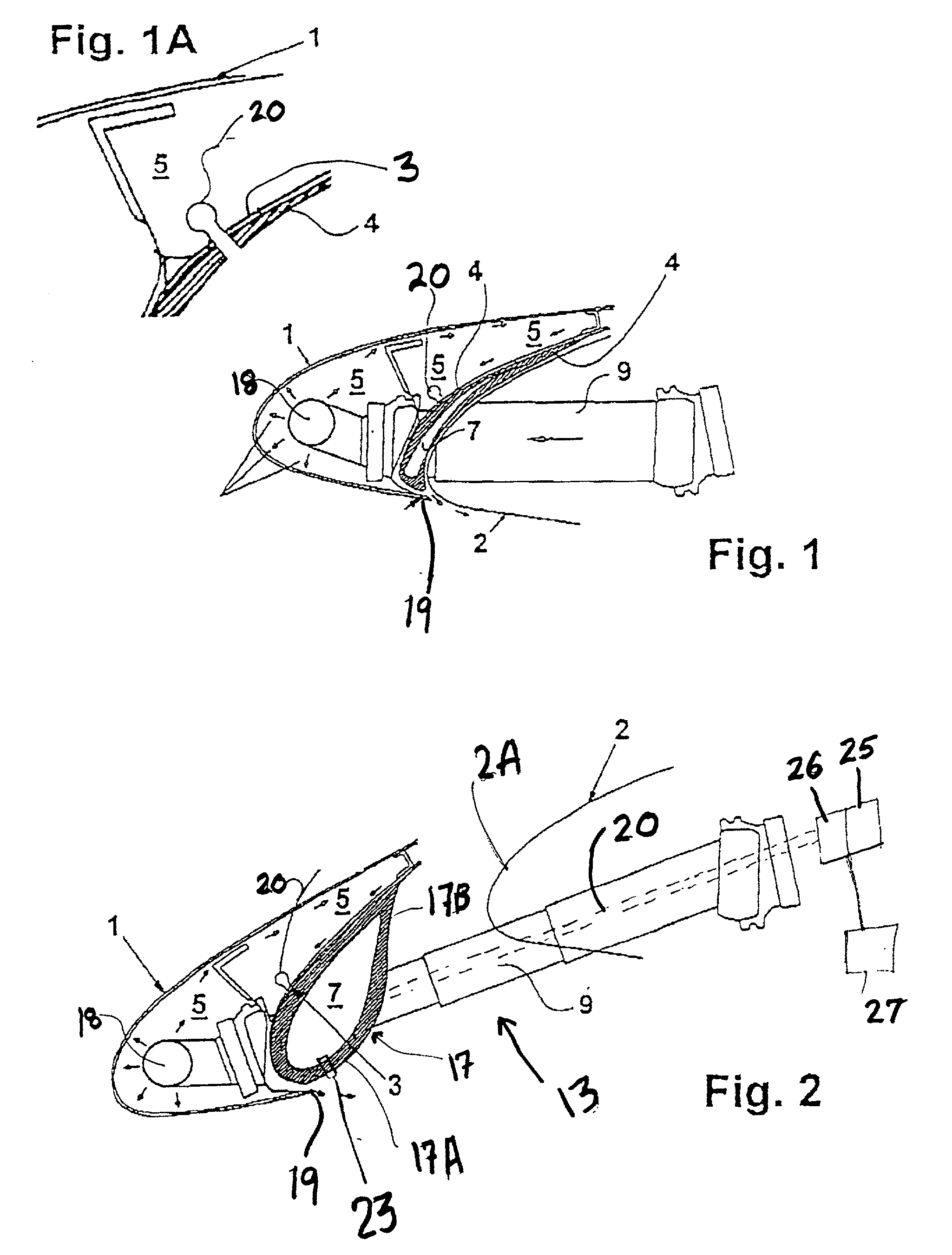
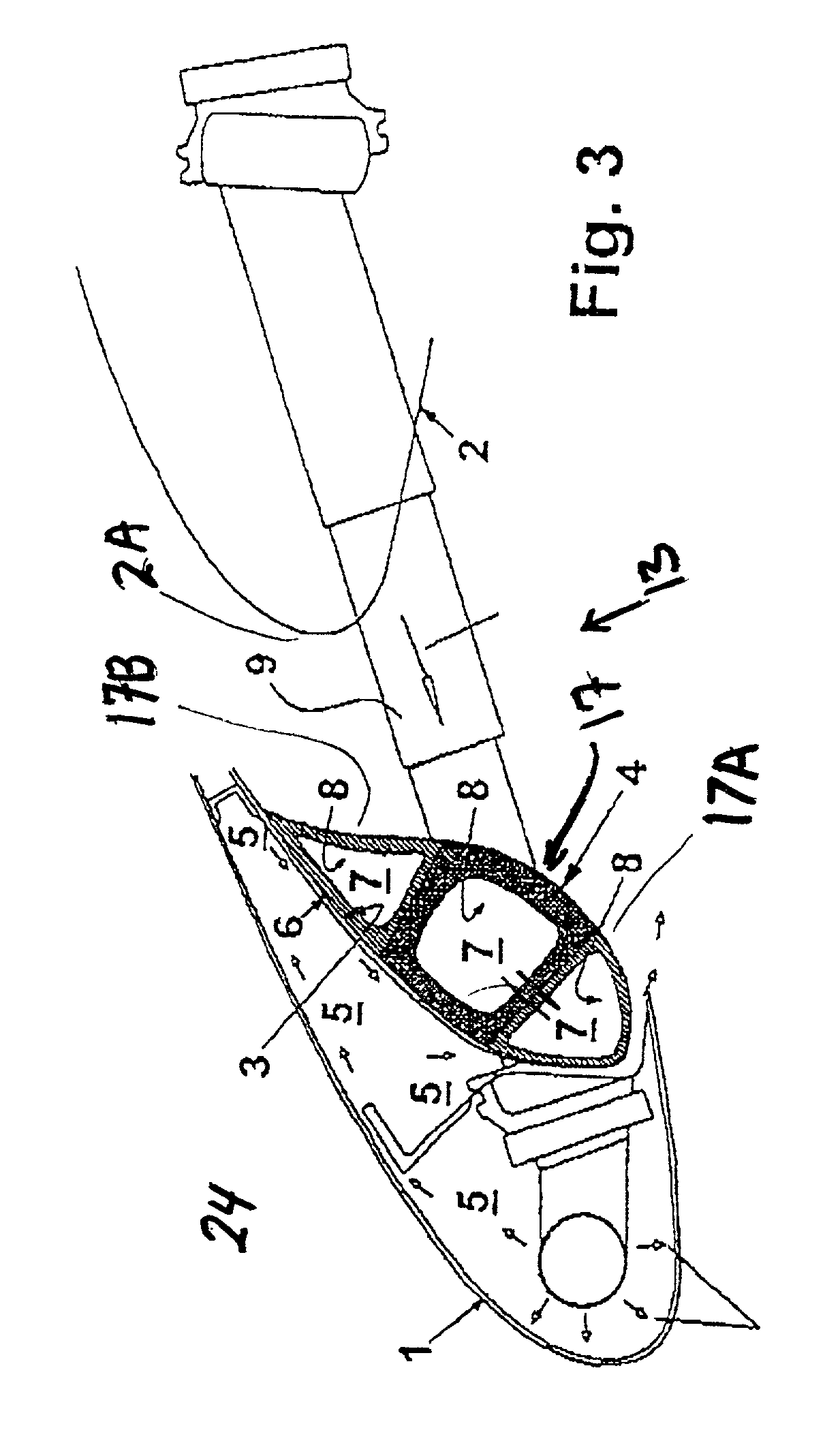
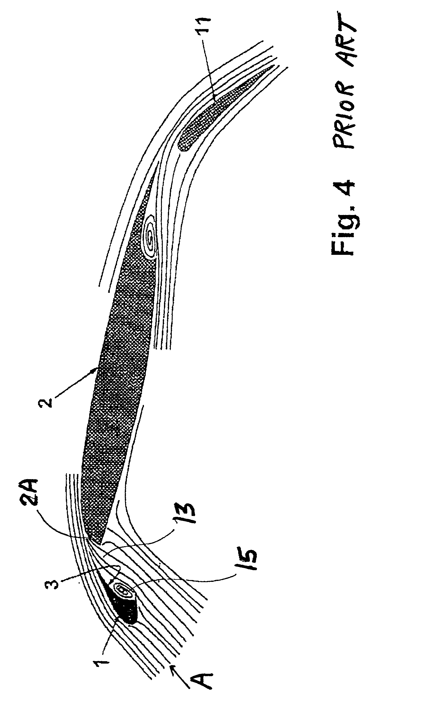
[0027] The general structure of a main wing 2 with an extended high-lift slat 1 and an extended landing flap 11, as well as the aerodynamic flow streamlines A associated therewith, in a conventional arrangement, have been discussed above in connection with FIG. 4. The point of the invention is especially to avoid or reduce the formation of the vortex 15 along the slat 1 while improving the aerodynamic configuration of the slat air gap 13 when the slat 1 is in the extended position, while still allowing a proper full retraction of the slat 1 against the leading edge nose 2A of the main wing 2. The inventive arrangement shall not have disadvantageous influences on the aerodynamic characteristics, such as the lift and the aerodynamic resistance, but rather actually improves these aerodynamic characteristics.

[0028] The inventive structural arrangement will now be described in connection with FIGS. 1 to 3. The key components of the inventive structural arrangement are a hollow displaceme...


PUM


Abstract

A hollow expandable and contractible displacement element is secured onto the concave rear surface of a slat facing the leading edge of an aircraft wing. A bleed air line supplies engine bleed air into the hollow displacement element to selectively expand or contract the displacement element, which is preferably elastically expandable. When the slat is extended, the displacement element is expanded to fill-out the concave cavity on the rear surface of the slat so as to prevent formation of a vortex in the slat air gap and thereby to reduce aero-acoustic noise. When the slat is retracted, the displacement element is contracted to be conformingly accommodated in the sickle-shaped space between the slat and the leading edge of the wing.

Description

PRIORITY CLAIM[0001] This application is based on and claims the priority under 35 U.S.C. .sctn.119 of German Patent Application 100 19 185.1, filed on Apr. 17, 2000, the entire disclosure of which is incorporated herein by reference.[0002] The invention relates to a structural arrangement for aerodynamic noise reduction in connection with leading edge slats on the wings of commercial transport aircraft. Particularly, the structure provides an aerodynamic effect on a wing slat in order to reduce the noise generated by air flowing around the slat, and through the air gap between the slat and the leading edge of the wing, especially during take-off and landing phases of flight of an aircraft.BACKGROUND INFORMATION[0003] Various noise sources contribute to the total noise generated during the flight of a modern commercial transport aircraft.[0004] Among the various noise sources, aero-acoustically generated noise that results from the flow pattern of air around the aircraft structure i...

Claims


Application Information

Patent Timeline
IPC IPC(8): B64C1/40B64C3/46B64C9/24B64C21/04B64C23/00B64D15/04
CPCB64C3/46B64C9/24B64D15/04Y02T50/145Y02T50/166Y02T50/32B64C2230/06B64C2230/14B64C2230/20Y02T50/10Y02T50/30
Inventor GLEINE, WOLFGANGMAU, KNUTCARL, UDO
Owner AIRBUS OPERATIONS GMBH
Why Eureka
Try Eureka