Multiple pressure sensors per finger of glove for virtual full typing

Inactive Publication Date: 2001-11-15
US PHILIPS CORP
View PDF1 Cites 65 Cited by
  • Summary
  • Abstract
  • Description
  • Claims
  • Application Information

AI Technical Summary

Benefits of technology

0004] It is an object of the invention to provide a

Problems solved by technology

This portion is susceptible to stretching when the

Method used


Image

  • Multiple pressure sensors per finger of glove for virtual full typing
  • Multiple pressure sensors per finger of glove for virtual full typing
  • Multiple pressure sensors per finger of glove for virtual full typing

Examples


Example

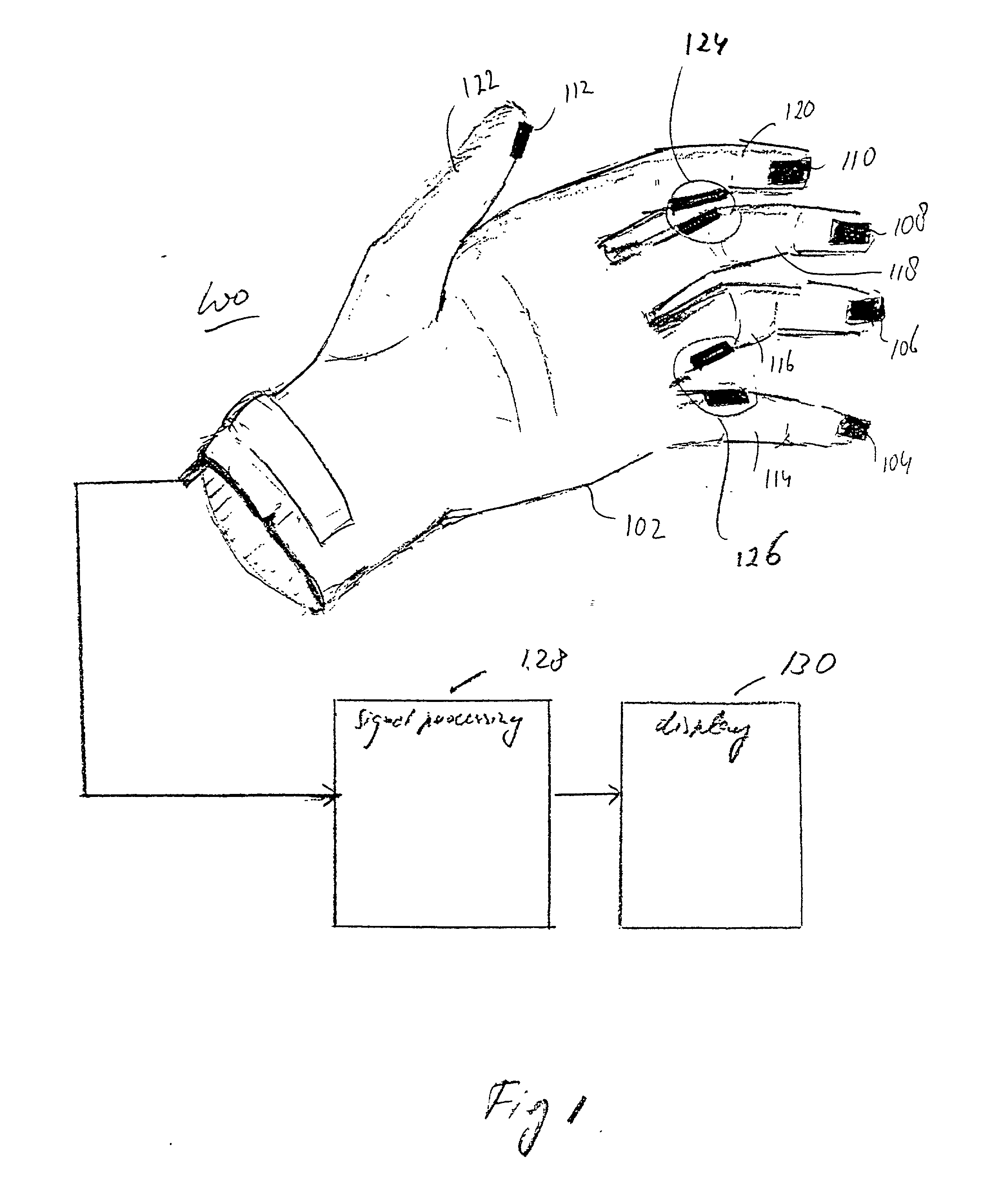
[0018] FIG. 1 is a block diagram with main components of a system 100 according to the invention. System 100 comprises an apparatus 102, here a glove, with devices 104, 106, 108, 110 and 112 mounted to fingers 114, 116, 118, 120 and a thumb 122, respectively. The user wears a pair of gloves for ten-finger typing, but FIG. 1 shows only left-hand glove 102 for clarity. The right-hand glove (not shown) is functionally similar to glove 102. Each of devices 104-110 has a respective first sensing sub-system (not shown here). Each of the subsystems discriminates between stimuli sensed at different locations at the corresponding one of devices 104-110. Each sub-system generates a specific signal corresponding to a stimulus sensed at a specific one of the locations. A specific sensitive location at a particular finger of glove 102 corresponds to a unique key of an alphanumeric keyboard. This is further explained below with reference to FIG. 2. In this example, device 112 at thumb 122 has a s...


PUM


Abstract

A glove has an array of pressure sensors mounted longitudinally at the finger-tips. When touching a rigid surface with the glove, different sensors are being activated dependent on the orientation of the finger tip relative to the surface. This configuration enables interacting with a virtual keyboard having multiple rows of keys.

Description

[0001] The invention relates to a system for processing information comprising an apparatus for manually controlling information input.[0002] Such a system is known from U.S. Pat. No. 5,581,484, incorporated herein by reference. The known system has a finger-mounted input device for manually entering information into a computer. The device uses a pressure sensor and a pair of acceleration sensors removably attached to the finger tip of a user. The pressure sensor senses a pressure when the finger presses against an object, e.g., a table surface. The acceleration sensors measure the acceleration of the finger. The sensors are mounted in a flexible glove. The signals of the sensors are relayed to a computer that calculates the relative position of the finger. Twice integrating an acceleration measured gives a coordinate of the current position of the finger relative to a begin position. The pressure sensor is used to validate the signal of the acceleration sensors. The known system al...

Claims


Application Information

Patent Timeline
IPC IPC(8): G06F3/02G06F3/00G06F3/01
CPCG06F3/014
Inventor VANCE, SCOTTMIGACHYOV, LARISAFU, WAYNE HONHAJJAR, IRA E.GRANT, JASON TRAVIS
Owner US PHILIPS CORP
Why Eureka
Try Eureka