Bo field drift correction in a temperature map generated by magnetic resonance tomography

Inactive Publication Date: 2009-04-16
SIEMENS HEALTHCARE GMBH
View PDF5 Cites 30 Cited by
  • Summary
  • Abstract
  • Description
  • Claims
  • Application Information

AI Technical Summary

Benefits of technology

[0029]If, as described above, the device includes a separate reference acquisition coil for acquisition of raw data for reference phase images, this reference acquisition coil is preferably combined with an image acquisition coil into a permanently connected module. In addition or as an alternative, the phantom is integrated with the associated acquisition coil (i.e. with the reference acquisition coil, in the event that one is p

Problems solved by technology

A variation of the B0 field also disadvantageously leads to a change of the proton resonance frequency to which the acquisition of a temperature map is tied (in terms of measurement).
An error in the resulting temperature map that normally grows with increasing distance between the acquisition points in time results due to the B0 drift.
Both methods for correcting the influence of the B0 field drift are relatively error-prone.
In particular, a displacement of the phantom or—if the correction region was defined in the patient body—a change of the patient position between the acquisition points in time can t

Method used


Image

  • Bo field drift correction in a temperature map generated by magnetic resonance tomography
  • Bo field drift correction in a temperature map generated by magnetic resonance tomography
  • Bo field drift correction in a temperature map generated by magnetic resonance tomography

Examples


Embodiment Construction

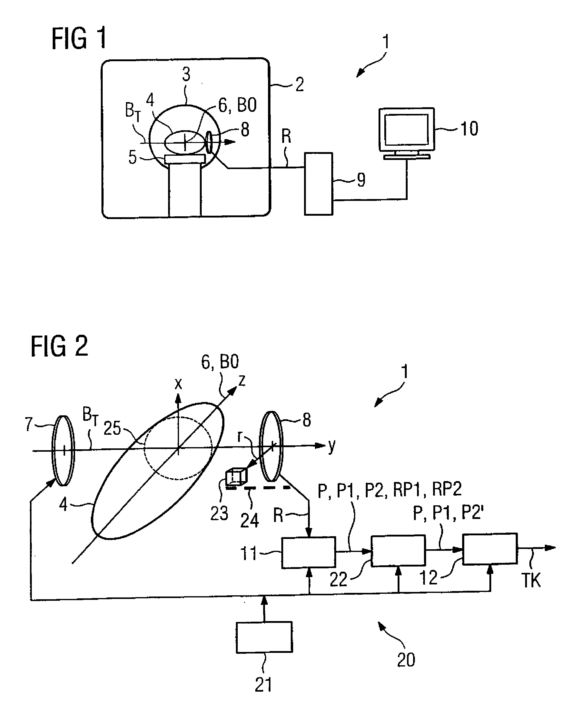
[0037]The magnetic resonance tomography apparatus 1 shown in FIG. 1 has a scanner 2 with a tunnel or bore 3 therein into which a patient body 4 can be inserted as an examination subject for the purpose of image data acquisition. A patient table 5 is provided to support the patient body 4.

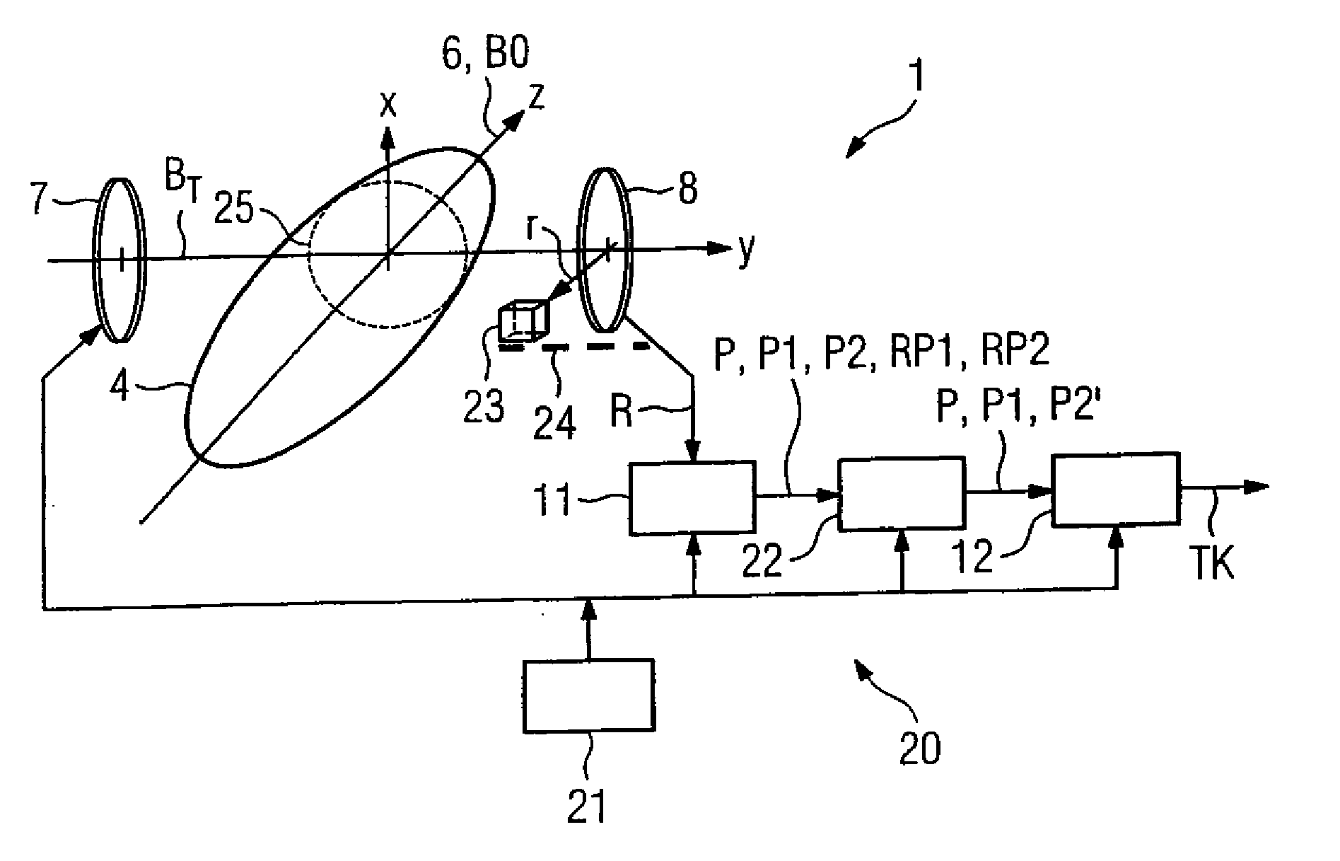
[0038]The scanner 2 contains (is not shown) magnetic coils with which a basic magnetic field B0 aligned parallel to a tunnel axis 6 is generated in the tunnel 3. The direction predetermined by the tunnel axis 6 is subsequently also designated as the z-direction (FIG. 2).

[0039]The scanner 2 furthermore contains gradient coils by means of which one or more magnetic gradient fields can be superimposed on the constant basic magnetic field B0. The magnetic field strength of each gradient field decreases or increases in a defined manner in the z-direction and / or perpendicular thereto (x-direction, y-direction). A specific spatial region within the patient body 4 is able to be selected by means of these gr...


PUM


Abstract

In a method to correct a B0 field drift in a temperature map exposure obtained by magnetic resonance tomography as well as a device to implement such a method, a magnetic resonance phantom is placed at a stored, marked reference position relative to an acquisition coil. A first reference phase image of the phantom is automatically acquired in the acquisition of a first phase image of an examination subject in the unheated state. A second reference phase image of the phantom is automatically acquired in the acquisition of a later second phase image of the examination subject. The phase images are adapted to one another according to the requirements of a calibration of the associated reference phase images.

Description

BACKGROUND OF THE INVENTION[0001]1. Field of the Invention[0002]This invention concerns a method for correcting a B0 field drift in a temperature map exposure produced by means of magnetic resonance tomography. The invention furthermore concerns a device to implement such a method.[0003]2. Description of the Prior Art[0004]An image representation of an examination subject (in particular of a patient body) that graphically reproduces a spatial distribution of the temperature or of a temperature difference within the examination subject is designated as a temperature map. Such a temperature map can be acquired by magnetic resonance (MR) tomography by interaction of the patient with an MR scanner. The presentation of temperature maps that show the temporal change of the temperature distribution within a patient body is a central component of a successful implementation of a tumor ablation in interventional radiology. In order to kill the tumor tissue, the tumor to be removed is heated ...

Claims


Application Information

Patent Timeline
IPC IPC(8): G01R33/38
CPCA61B5/015A61B5/055G01R33/58G01R33/4814G01R33/56563G01R33/4804
Inventor ROLAND, JOERG
Owner SIEMENS HEALTHCARE GMBH
Why Eureka
Try Eureka