Cotton candy making machine
a candy making machine and candy technology, applied in the field of candy making machines, can solve the problems of spoiled inner surface of the basin, high maintenance cost, and spoiled raw materials
- Summary
- Abstract
- Description
- Claims
- Application Information
AI Technical Summary
Problems solved by technology
Method used
Image
Examples
first embodiment
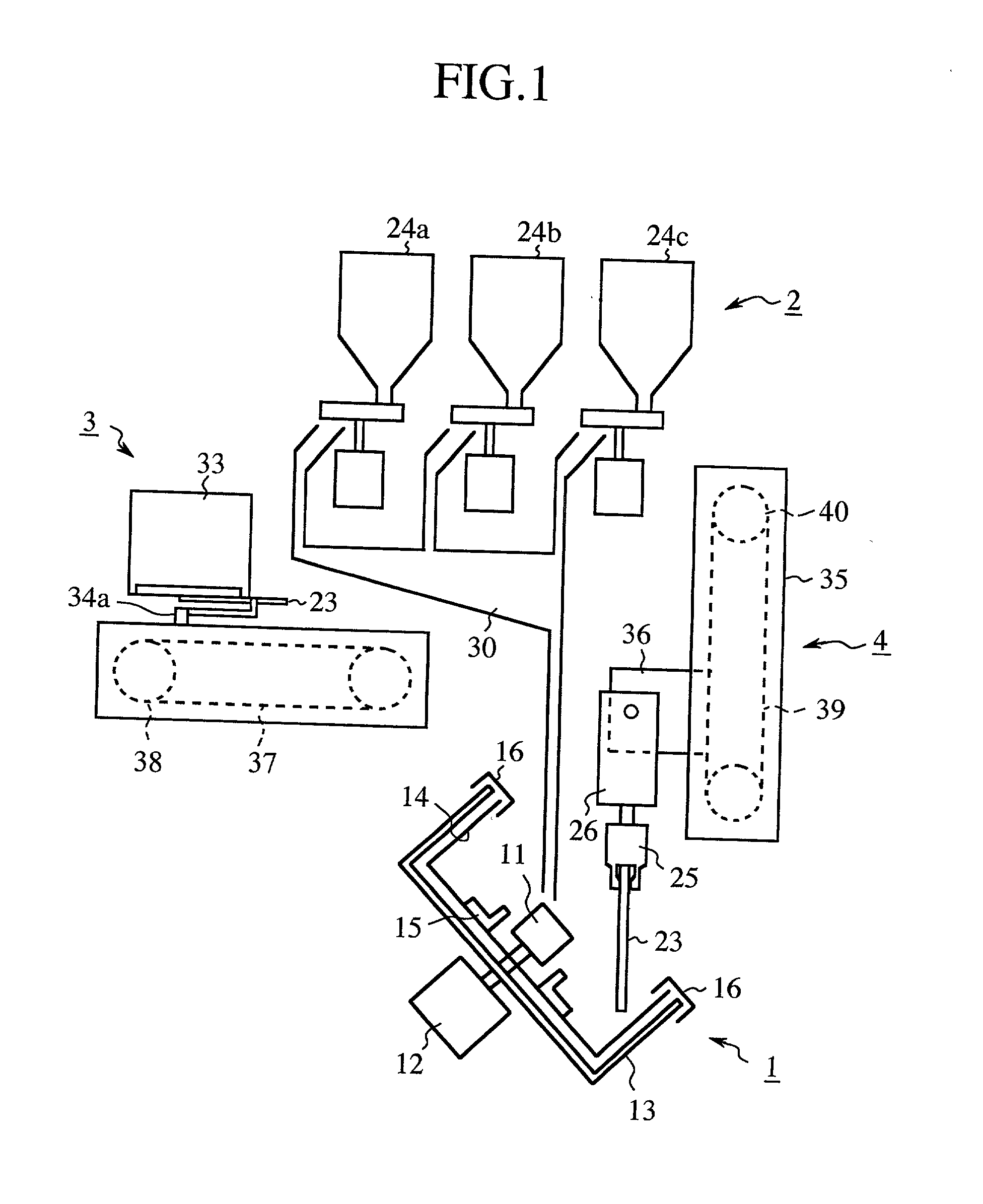
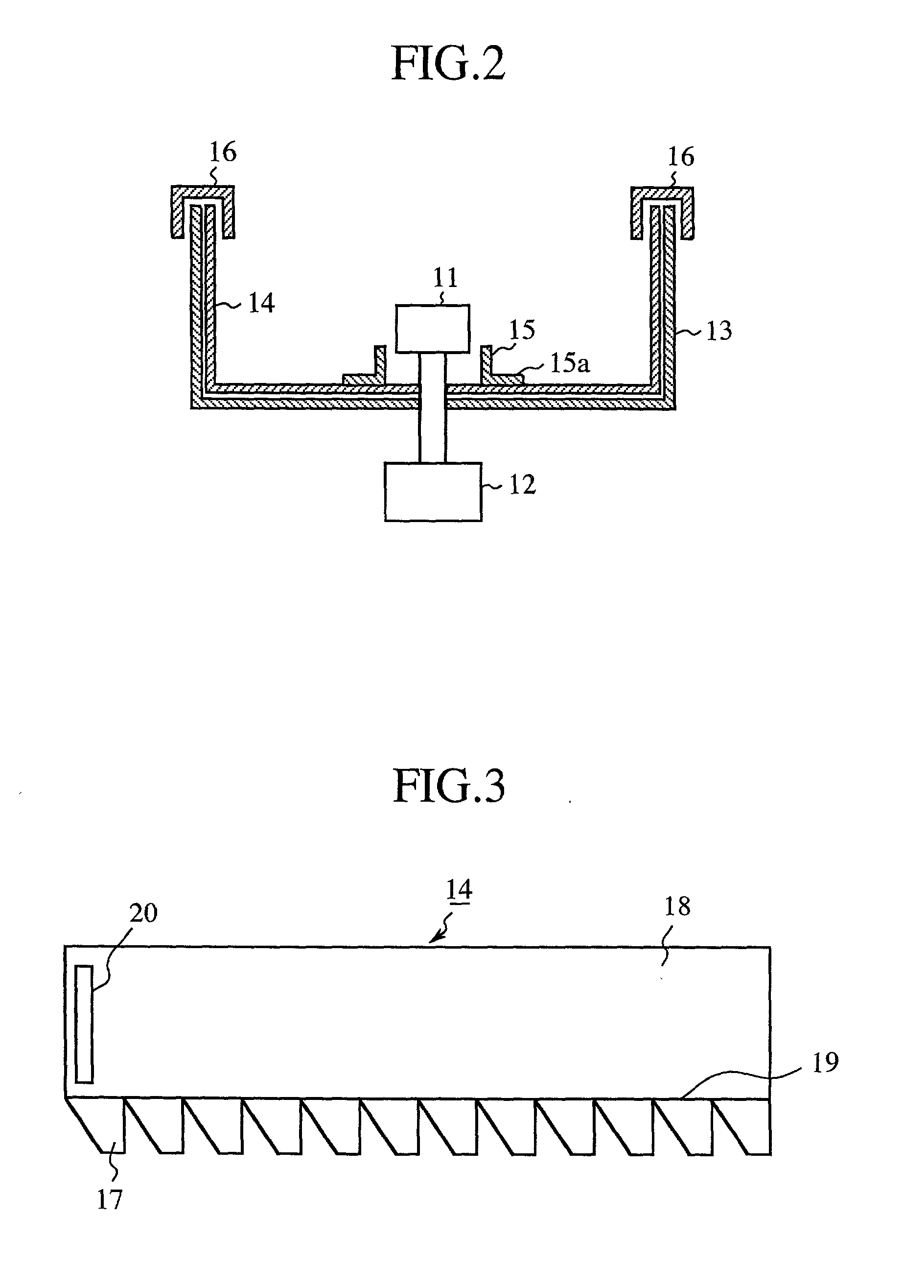
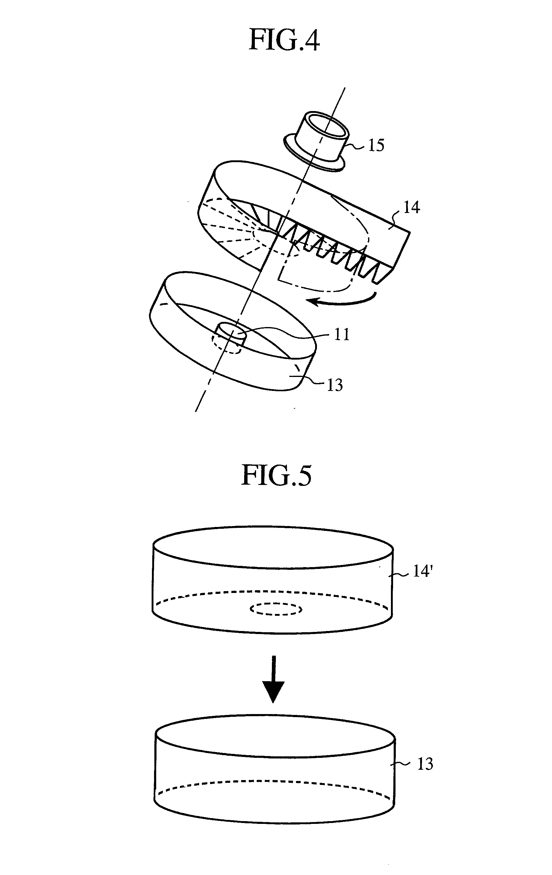
[0083] FIG. 10, FIG. 11A, and FIG. 11B are schematic diagrams that illustrate the relationship among the floss taking-up stick 23, the rotary pot 11, and the basin 13 with respect to their relative positions. In the figures, the reference numeral 11 denotes a rotating port, 13 denotes a basin, 14 denotes a soil-preventing paper, 23 denotes a floss taking-up stick, 25 denotes a holder for holding the floss taking-up stick 23, 26 denotes a chuck for holding one end of the stick 23, which is able to rotate by a motor (not shown) included in the holder 25, and the reference numeral 100 denotes a cotton candy. In the figure, the alphabet "A" denotes a line parallel to a rotation axis of the floss taking-up stick 23 hereinafter, the line is simply referred to as a rotation axis of the floss taking-up stick 23). Also, the alphabet "C" denotes a blast of air blown from the rotary pot 11. In the first embodiment, therefore, the means for taking up the cotton candy is constructed of the stick...
embodiment 2
[0100] FIG. 15 is a schematic diagram that illustrates a general configuration of a cotton candy making machine as a second embodiment (Embodiment 2) of the present invention. In this embodiment, the cotton candy making machine is constructed of the same components as those of the first embodiment shown in FIG. 1, except that a container (e.g., cup, bowl, or box) is used instead of a floss taking-up stick. In the figure, the reference numeral denotes a cotton candy making section, 2 denotes a raw material supplying section for supplying sugar (granular sugar) as the raw material to the cotton candy making section 1, 50 denotes a means for making a cotton candy 100 in roughly spherical form by twirling threaded sugar on a stick (hereinafter, referred to as a floss taking-up section), 51 denotes a means for removing the cotton candy from the floss taking-up section 50 (hereinafter, referred to as a cotton candy extruding section), and 52 denotes an up-and-down section for moving the f...
second embodiment
[0112] FIGS. 19 and 20 illustrate a modified example of the second embodiment in which two or more leaf springs 67 are provided on the tip of a floss taking-up stick 58' in addition to the leaf springs 59 for supporting a cotton candy. FIG. 19 illustrates a state of forming a cotton candy on the stick 58' and FIG. 20 illustrates a state of releasing the cotton candy from the stick. In this case, just as in the case of shown in FIG. 17, the shaft 62 is moved upward by the rotation of the driving motor 61, so that the extruding plate 60 is positioned at the upper side of the stick 58' and the leaf springs 59, 67 are not pressed by the edge of the opening 64 formed on the extruding plate 60. Thus, the leaf springs 59, 67 are extended outwardly in the direction of the radius of the stick 58', allowing a sufficient radial clearance between each of the leaf springs 59 and the peripheral surface of the stick 58' and forming a supporting structure that prevents the fall of the growing cotto...
PUM
| Property | Measurement | Unit |
|---|---|---|
| Angle | aaaaa | aaaaa |
| Radius | aaaaa | aaaaa |
Abstract
Description
Claims
Application Information
 - R&D
- Intellectual Property
- Life Sciences
- Materials
- Tech Scout
- Unparalleled Data Quality
- Higher Quality Content
- 60% Fewer Hallucinations
Browse by: Latest US Patents, China's latest patents, Technical Efficacy Thesaurus, Application Domain, Technology Topic, Popular Technical Reports.
© 2025 PatSnap. All rights reserved.Legal|Privacy policy|Modern Slavery Act Transparency Statement|Sitemap|About US| Contact US: help@patsnap.com


