Heat exchanger with tubes suspended into a lower end plate allowing thermal movement of the tubes

a technology of heat exchanger and tube, which is applied in the direction of indirect heat exchanger, heat transfer modification, lighting and heating apparatus, etc., can solve the problems of high repair cost, insufficient design effect, and extreme stress on materials

Inactive Publication Date: 2001-11-22
SANDVIK INTELLECTUAL PROPERTY AB
View PDF0 Cites 11 Cited by
  • Summary
  • Abstract
  • Description
  • Claims
  • Application Information

AI Technical Summary

Benefits of technology

0008] A prime objective of the present invention is thus to produce a heat ex

Problems solved by technology

These conditions result in utmost severe stresses for the materials in the heat exchanger.
Occasionally the tube plate has failed to stand up to the heavy loads to which

Method used


Image

  • Heat exchanger with tubes suspended into a lower end plate allowing thermal movement of the tubes
  • Heat exchanger with tubes suspended into a lower end plate allowing thermal movement of the tubes
  • Heat exchanger with tubes suspended into a lower end plate allowing thermal movement of the tubes

Examples


Embodiment Construction

[0017] FIG. 3 shows how the lower parts of heat exchanger tubes 13 pass through a double walled tube plate 18A in the lower region of the heat exchanger.

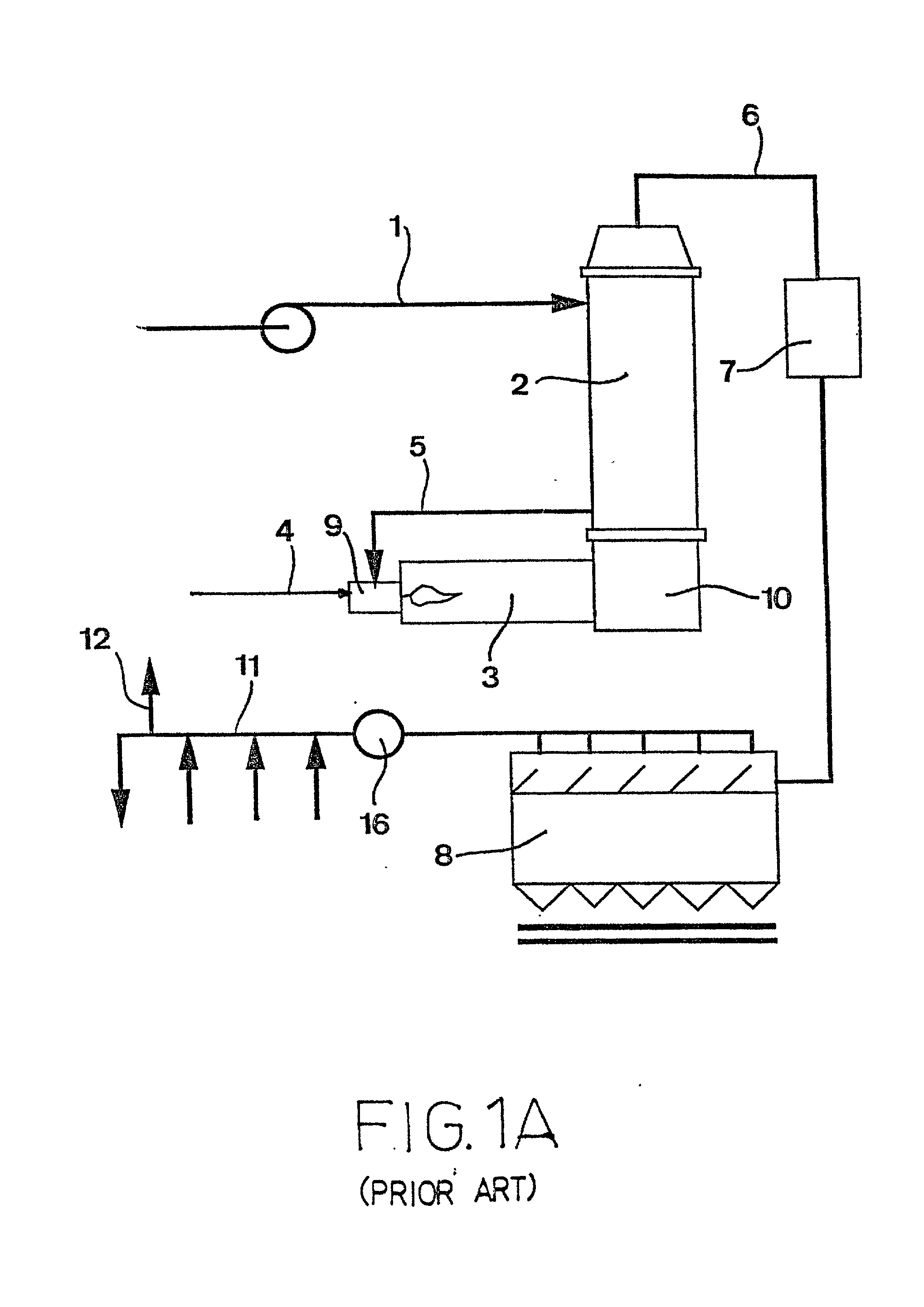
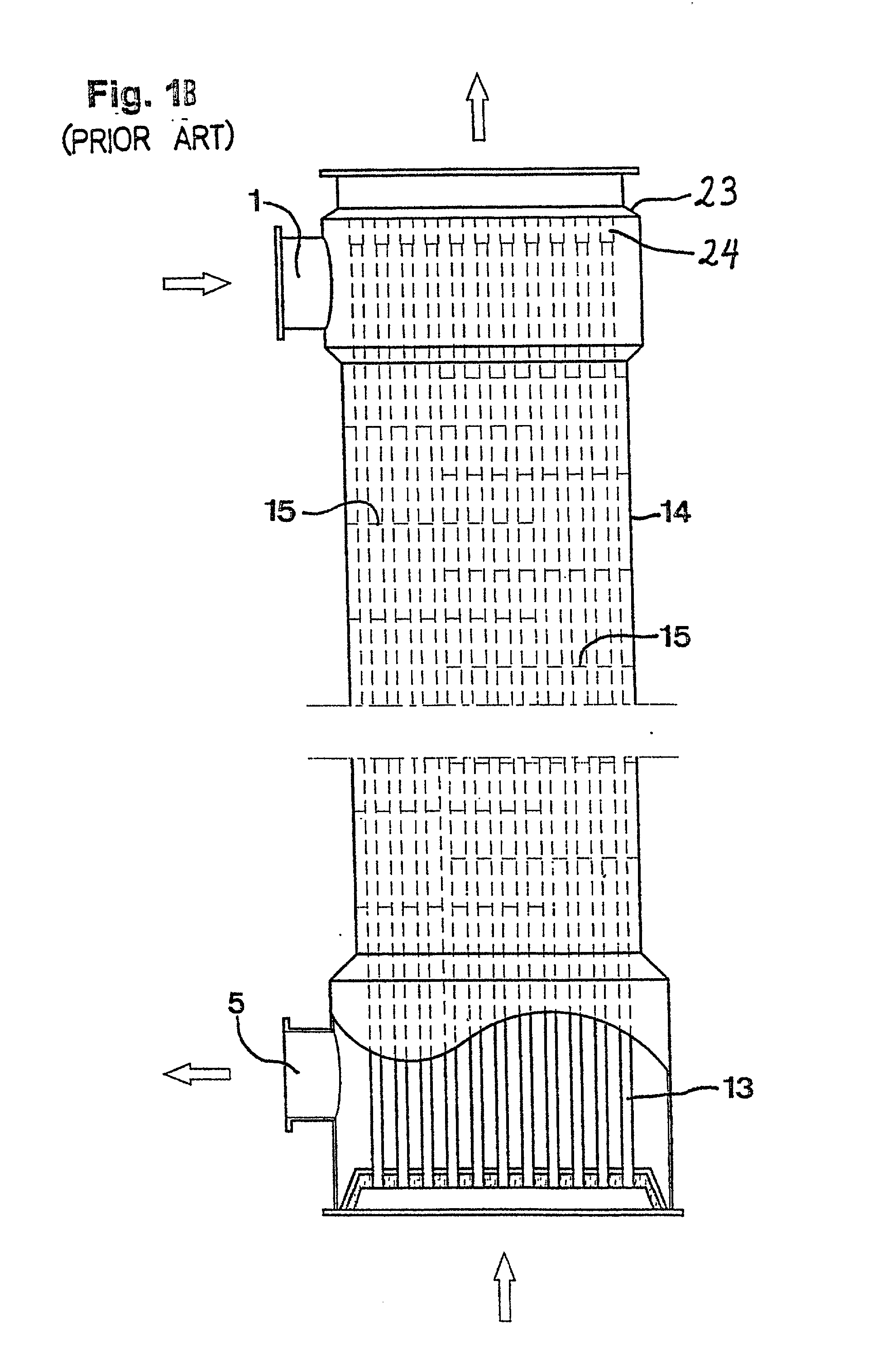
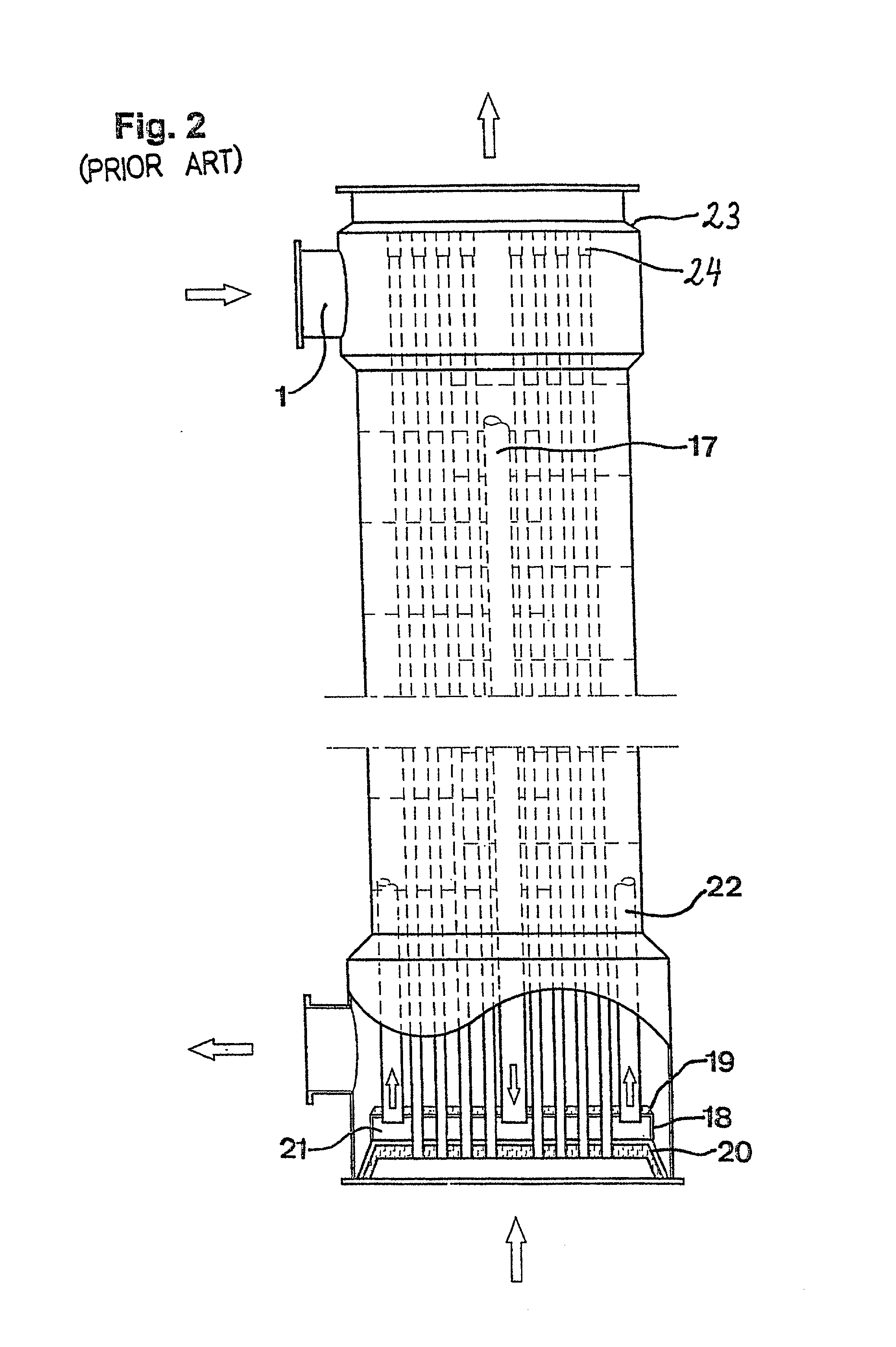
[0018] Such an arrangement would be employed in lieu of an arrangement disclosed in Swedish Patent Applications 9504344-4 and 9603739-5 which were discussed earlier in connection with FIGS. 1-2, wherein the feet of the heat exchanger tubes 13 were securely welded to a tube plate, and upper parts of the tubes extended in collars or compensators disposed at the upper end of the heat exchanger, in order to permit thermal expansions or contractions of the tubes.

[0019] That known design has been changed in accordance with the present invention in such a way that the tubes 13 now hang from their upper portions instead of having their lower parts standing on a plate. In order to hang the tubes from their upper portion they are simply welded at the point where they pass through a hole in a horizontal suspension wall 13A which is located at ...


PUM


Abstract

A tube heat exchanger intended to be used for the production of carbon black, includes a cylindrical closed chamber having a plurality of tubes which extend through the entire, essentially cylindrically shaped chamber. Upper end of the tubes are attached to an upper end wall, preferably by welding, and hang down to a tube plate. The tube plate equipped with compensating devices to enable thermally induced expansions and contractions of the tubes to occur.

Description

[0001] This is a continuation-in-part of International Application Serial No. PCT / SE98 / 00952, filed May 20, 1998 and which designated the United States.[0002] The present invention relates to a tube heat exchanger and a tube plate for supporting the tubes of a tube heat exchanger. Specifically the invention relates to a heat exchanger with vertical tubes of considerable lengths having weights which in combination with high temperature subject the tubes themselves and the tube plate to considerable stresses. This tube plate is particularly suitable for use in tube heat exchangers which produce carbon black.[0003] Carbon black is the term used for the finely divided powder forms of carbon which are produced by incomplete combustion or thermic degradation of natural gas or mineral oil. Depending on the method of production, different types of carbon black arise, namely so called channel black, furnace black and pyrolysis black (also called thermal black). Furnace black is by far the mo...

Claims


Application Information

Patent Timeline
IPC IPC(8): F28D7/16F28F9/02F28F9/18
CPCF28F9/0236F28F9/0229
Inventor BERGLUND, GORANERIKSSON, ULF
Owner SANDVIK INTELLECTUAL PROPERTY AB
Why Eureka
Try Eureka