Instantaneous dual band fluorescence detection systems

a detection system and dual band technology, applied in the direction of fluorescence/phosphorescence, analysis by material excitation, instruments, etc., can solve the problems of instrument cost burden, sample aging, and degrade the measurement of flux ratio between bands

Inactive Publication Date: 2001-11-29
CAMBRIDGE RES & INSTR
View PDF0 Cites 43 Cited by
  • Summary
  • Abstract
  • Description
  • Claims
  • Application Information

AI Technical Summary

Benefits of technology

[0016] It is a further object of the present invention 1 to provide for fluorescence polarization measurements with high accuracy, for either a single probe or for two probes at once.
[0028] The ability to obtain dual-band spectral data without a significant burden in cost, throughput, or optical efficiency, makes it practical to obtain a second band for purposes other than imaging two probes. For example, the instrument may be set to image a primary band corresponding to the probe of interest, and a secondary band corresponding to background fluorescence. Having an in-situ measure of background fluorescence at the secondary band, together with some knowledge of the spectral distribution of background fluorescence, enables improved background correction at the primary (probe) band. Thus even single-probe measurements can be improved by the present invention.

Problems solved by technology

However, this is undesirable for several reasons.
First, it takes twice as long as a single-band measurement, which can result in sample aging.
Finally, lamp flicker and drift are a significant source of noise in fluorescent measurements, and will degrade the measurement of flux ratios between bands.
However, such instruments bear a cost burden due to the need for two detectors and readout electronics, plus beamsplitters.
This cost burden becomes even more significant if one wishes to make an imaging system of this type, using two pixelated detectors such as CCD detectors.
This registration must be handled carefully and while the approach is simple in theory, building such an instrument in practice tends to be demanding.
There is another problem with existing multiband fluorescence instruments.
The use of dielectric filters at non-normal incidence to sample the beam, or indeed anywhere in the instrument, can lead to systematic spectral and polarization errors.
In practice, problems are most likely present when one wishes to observe bands that are spectrally adjacent, or where one band is spectrally close to the excitation wavelength.
Such samples are not measured accurately by an instrument that uses dielectric filters to split off the beam to multiple detectors.
Thus the deficiencies of the prior art instruments are most likely to be germane, precisely when utilizing their dual-band readout capability to read dual-probe assays.
Such a dual-detector approach also would be less than optimal for measuring fluorescence polarization, due to the polarization sensitivity of the instrument.
There are several limitations to this instrument.
In addition to the complexity of this approach, the instrument can only collect light from a small region corresponding to the image of the spectrometer slit projected on the sample.
Thus its sensitivity is relatively low compared to instruments that can illuminate, and collect light from, extended regions such as sample spots or microtitre plate wells.
Further, the efficiency of gratings and prisms depends upon polarization state, which renders a dispersive instrument inherently ill-suited for fluorescence polarization assays

Method used


Image

  • Instantaneous dual band fluorescence detection systems
  • Instantaneous dual band fluorescence detection systems
  • Instantaneous dual band fluorescence detection systems

Examples


Embodiment Construction

[0041] Throughout the following, one state of polarization is termed h and its complement is v. These need not be literally horizontal and vertical, but either h or v must correspond to the major axis of the state of polarization used to excite the sample in any given measurement.

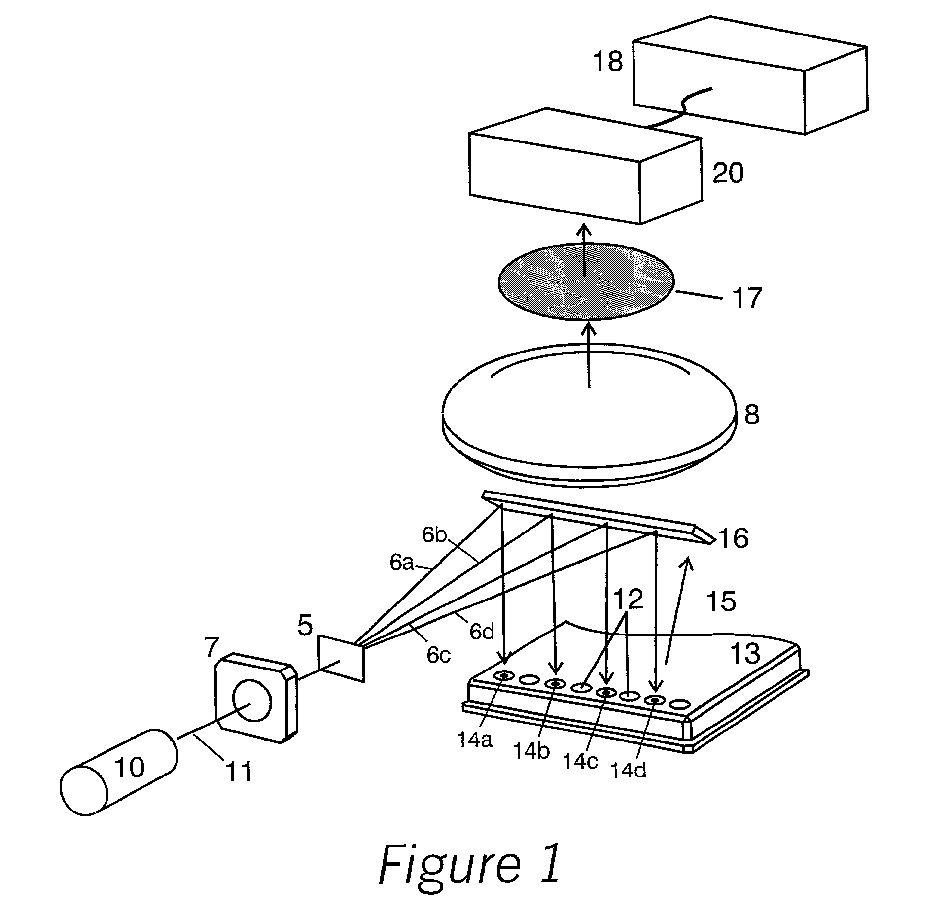
[0042] The term spectral band is used to refer to a set of wavelengths of light, either in the visible, infrared, or ultraviolet spectral region. The term probe is used to describe a substance that emits fluorescent light when optically excited, which enables measuring one or more properties of a sample, through observation of the brightness, spectral distribution, polarization, or combinations thereof, of the fluorescent emission. The term spot is used to describe a spatial region on the sample that is optically excited, as well as to describe the rays emanating from that region as they propagate through the optical system and form images thereof at a detector.

[0043] FIG. 1 shows an instrument in accordanc...


PUM

PropertyMeasurementUnit
thicknessaaaaaaaaaa
fluorescenceaaaaaaaaaa
fluorescence intensityaaaaaaaaaa

Abstract

An apparatus for performing fluorescence detection of two or more biochemical probes and / or fluorescence measurement of fluorescence intensity at two or more spectral bands of light emitted from at least one sample spot is disclosed. The apparatus simultaneously directs emitted fluorescent light from multiple probes and / or at multiple spectral bands to different spots on a single pixelated detector.

Description

[0001] 1. Field of the Invention[0002] The invention is directed toward instrumentation for biochemical assays, more particularly assays using fluorescence detection with two or more labels in the experiment; or assays requiring a ratiometric measurement of fluorescence intensity at two spectral bands.[0003] 2. Description of the Related Art[0004] Fluorescence assays that use multiple probes typically require measuring the fluorescence emission levels in two spectral bands, corresponding to the probes involved. Similarly, one may look in two bands to detect shifts in the spectrum of a single probe, if its emission spectrum is sensitive to environment. Examples of such probes include Indo, for pH sensing; or Acridine Orange to sense binding to RNA. In these cases, one wishes to use spectral ranges whose flux levels will be most sensitive to the spectral shift.[0005] In such measurements, one often seeks to compare the flux in levels between the bands with high precision. In an assay ...

Claims


Application Information

Patent Timeline
Patent Type & Authority Applications(United States)
IPC IPC(8): G01N21/64
CPCG01N21/6428G01N21/6445G01N21/6452G01N2021/6421G01N2021/6441G01N2021/6471
Inventor HOYT, CLIFFORD C.
Owner CAMBRIDGE RES & INSTR
Why Eureka
Try Eureka