Apparatus for and method of measuring thermal stress of concrete structure

a technology of concrete structure and thermal stress, which is applied in the direction of apparatus for force/torque/work measurement, structural/machine measurement, instruments, etc., can solve the problems of concrete structure cracks that deleteriously affect utility, water tightness and durability, and analytical methods that give inaccurate results for early-age concrete, etc. problem, problem is not readily solved, and problem of concrete whose physical properties cannot be clearly determined

Inactive Publication Date: 2001-12-13
KOREA ADVANCED INST OF SCI & TECH
View PDF0 Cites 36 Cited by
  • Summary
  • Abstract
  • Description
  • Claims
  • Application Information

AI Technical Summary

Problems solved by technology

Recently, active research has been directed to the development of cement which is free from generating heat upon hydration because the heat of hydration causes significant problems in constructing massive concrete structures or effecting high strength concretes.
In extreme cases, the thermal stress may cause cracks in concrete structures to deleteriously affect the utility, water tightness and durability thereof.
Because it makes assumptions on the behavior of all parameters, the analytical method is apt to give inaccurate results for early-age concrete, whose physical properties cannot be clearly determined.
This problem is also not readily solved by the experimental method using actual or model structures.
Additionally, the experimental method suffers from the disadvantage of requiring a large expenditure because an experiment must be carried out during the construction.
The testing apparatuses, most of which are manufactured in Germany or Japan, are very expensive and have difficulty in modeling actual thermal stresses generated in concrete structures.
Additionally, the apparatuses cannot detect the changes in thermal stress of the structure subjected to internal and external confinements.
Those apparatuses cannot effectively reflect the tendency.
Also, the testing apparatuses are economically unfavorable in that additional devices are required to describe the thermal change at some sites of the structure.

Method used


Image

  • Apparatus for and method of measuring thermal stress of concrete structure
  • Apparatus for and method of measuring thermal stress of concrete structure
  • Apparatus for and method of measuring thermal stress of concrete structure

Examples


experiment

[0031] Experiment Method

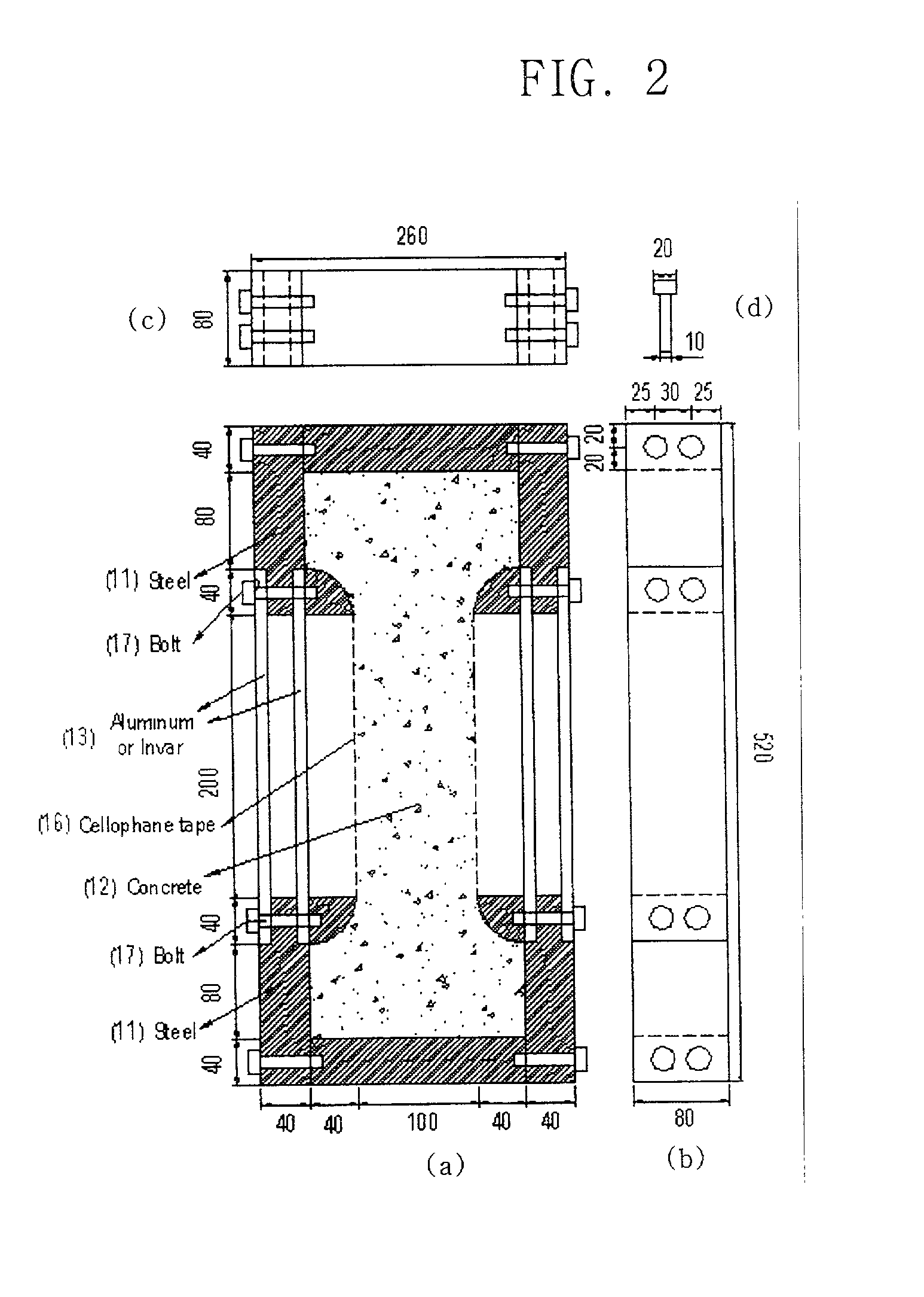
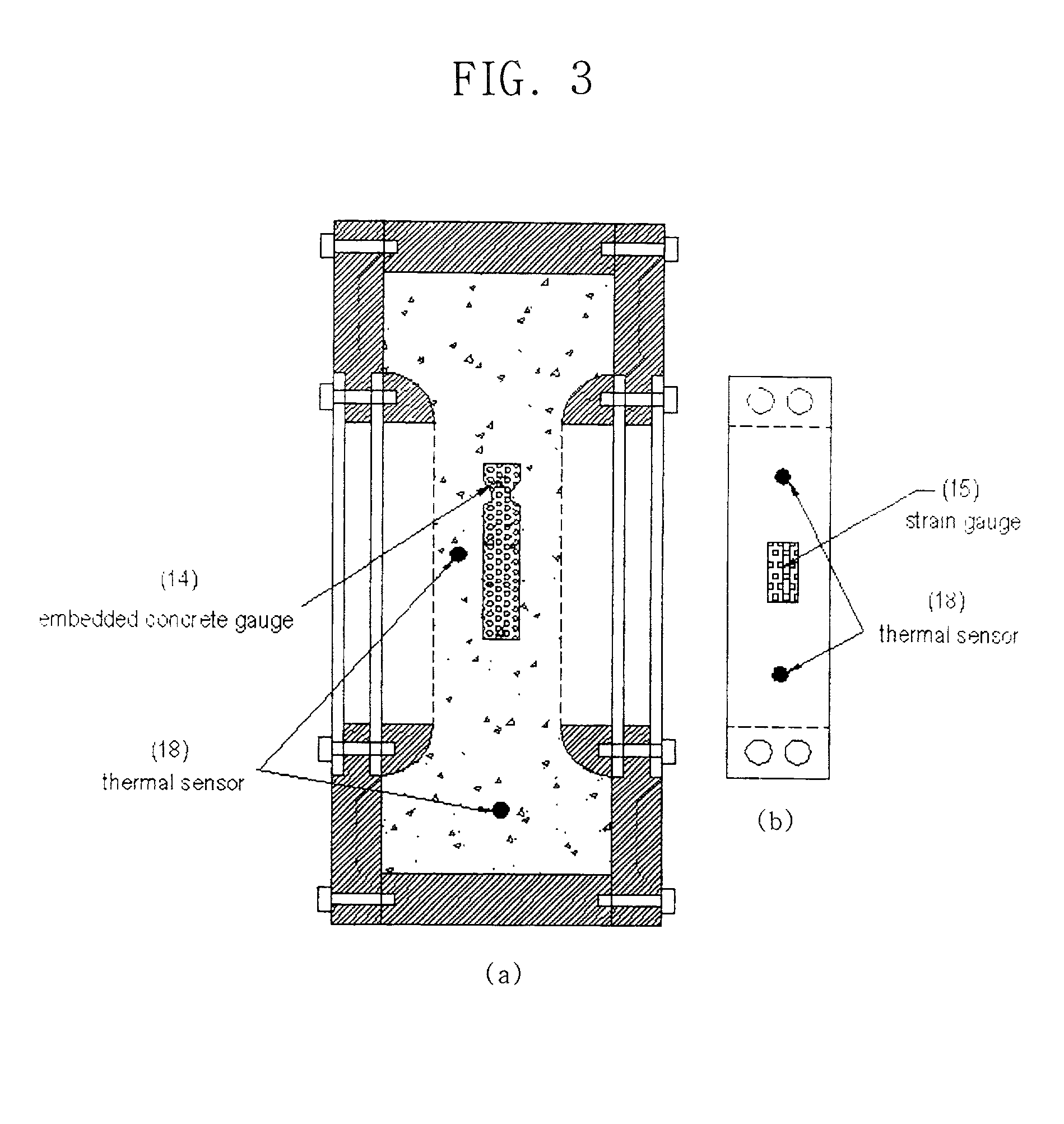
[0032] With reference to FIG. 3, a testing apparatus filled with concrete is shown in a cross sectional view (a) and in a side view (b). To measure the change in thermal stress of the concrete, as shown in FIG. 3, the testing apparatus is equipped with some meters. That is, a proper strain gauge 15 is attached to the metal plate with a concrete gauge 14 being embedded in the concrete. Thermal sensors 18 are provided inside the concrete and a temperature and humidity chamber to fit the concrete temperature into the programmed temperature. To prevent the concrete from undergoing plastic shrinkage and drying shrinkage, the chamber is programmed to keep its humidity at 85%. In addition, because the amount of the concrete to be applied to the apparatus is not large and the thickness of the applied concrete is only 80 mm, as seen in FIG. 2, the heat of hydration generated from the applied concrete 12 is too small to affect the concrete 12 when account is taken of t...


PUM

PropertyMeasurementUnit
humidityaaaaaaaaaa
thicknessaaaaaaaaaa
thermal stressesaaaaaaaaaa

Abstract

Disclosed are a testing apparatus for and a method of measuring thermal stresses of concrete structures. Overcoming the limitations that conventional analytical access techniques have, the apparatus opens a new way to conveniently measure the thermal stress attributable to the heat of hydration generated in concrete structures indoors. Using a material different in coefficient of thermal expansion from concrete, the apparatus can directly measure the change in thermal stress of the concrete which is subjected to internal and/or external confinement. By using various materials, the thermal stress which varies depending on the confinement extent can be inferred. Additionally, an accurate prediction of the thermal stresses generated actually in concrete can be obtained, reflecting unclear physical properties of early-age concrete.

Description

[0001] 1. Field of the Invention[0002] The present invention relates to an apparatus for and a method of measuring thermal stresses attributed to the heat of hydration generated from concrete structures, which can be used in the laboratory instead of conventional analytical techniques or experiments performed on actual concrete structure.[0003] 2. Description of the Prior Art[0004] Recently, active research has been directed to the development of cement which is free from generating heat upon hydration because the heat of hydration causes significant problems in constructing massive concrete structures or effecting high strength concretes. A concrete structure undergoes a certain thermal stress caused by the heat of hydration of cement, according to confining conditions given to its inner and outer portions. In extreme cases, the thermal stress may cause cracks in concrete structures to deleteriously affect the utility, water tightness and durability thereof.[0005] It is, therefore,...

Claims


Application Information

Patent Timeline
Patent Type & Authority Applications(United States)
IPC IPC(8): G01L5/00G01L1/00G01M99/00G01N3/02G01N3/04G01N25/16G01N33/38
CPCG01N3/04G01N25/16G01N33/383G01N2203/0222G01N2203/0268G01N2203/0284G01N2203/0405G01L1/00
Inventor KIM, JIN KEUNJEON, SANG EUNKIM, KOOK HAN
Owner KOREA ADVANCED INST OF SCI & TECH
Why Eureka
Try Eureka