An antenna device, a method for manufacturing an antenna device and a radio communication device including an antenna device

a technology of antenna device and antenna device, which is applied in the direction of antenna support/mounting, radiating element structure, electrical apparatus, etc., can solve the problems of difficult placement of antenna device in transceiver, difficult placement of antenna device in receiver, and antenna device carried on flexible substrate does not ensure stability

Inactive Publication Date: 2002-01-03
ALLGON
View PDF0 Cites 136 Cited by
  • Summary
  • Abstract
  • Description
  • Claims
  • Application Information

AI Technical Summary

Problems solved by technology

However, due to its flexibility the substrate is difficult to place in a transceiver.
Also here, it is difficult to place the antenna device in the receiver, since its base is flexible.
Further, the antenna device carried on a flexible substrate does not ensure stability.

Method used


Image

  • An antenna device, a method for manufacturing an antenna device and a radio communication device including an antenna device
  • An antenna device, a method for manufacturing an antenna device and a radio communication device including an antenna device
  • An antenna device, a method for manufacturing an antenna device and a radio communication device including an antenna device

Examples


Embodiment Construction

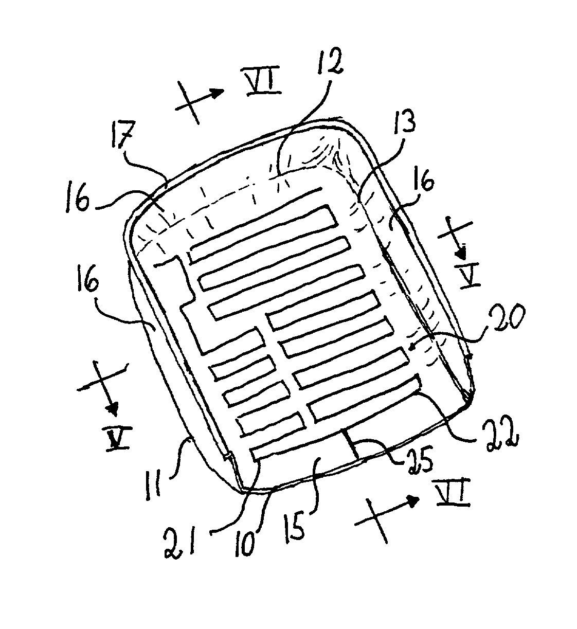
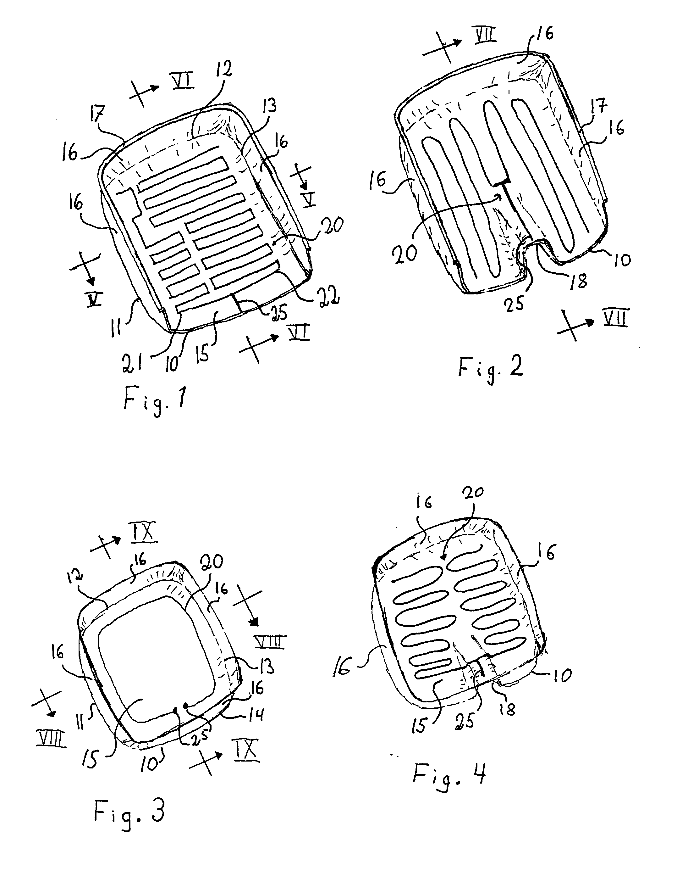
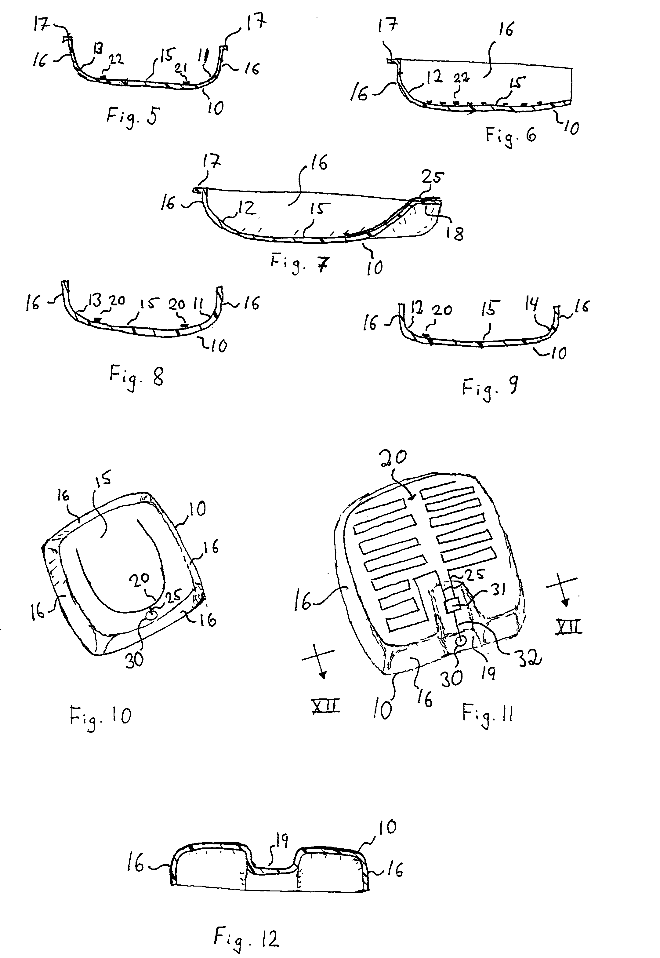
[0039] With reference to FIG. 1, a radiating structure 20 on a carrier 10 included in an antenna device for transmitting and receiving RF waves in connection to a radio communication device, according to the invention is diagrammatically shown. The carrier 10 is relatively thin, having a thickness being in the range some tenth of a millimeter to a few millimeters, preferably 0.2-1 millimeter. Preferably the carrier 10 is made from a dielectric polymeric sheet-like material, which includes a band shaped material cut into suitable pieces. As seen in the figure, the carrier is formed so as to define upwardly curved portions 11-13 limiting an essentially planar or very smoothly curved portion 15. Around the curved portions 11-13 the carrier 10 continues in low wall portions 16. In FIG. 1 three curved portions 11-13 are shown, so as to leave one side of the essentially planar or very smoothly curved portion 15 open.

[0040] The sheet-like material from which the carrier is formed, is prefe...


PUM


Abstract

An antenna device for transmitting/receiving RF waves to be arranged in a radio communication device, comprising: a carrier (10) having first and second surfaces carrying a radiating structure (20) on the first surface; a feed portion (25) being connectable to transceiver circuits of the radio communication device and being arranged on the carrier (10) and forming a part of the radiating structure (20); and a ground plane means. The carrier has, in a first plane essentially perpendicular to the first surface, a cross section where the first surface exhibits at least a first curved portion (12). Further, the carrier has, in a second plane essentially perpendicular to the first plane and essentially perpendicular to the first surface, a cross section where the first surface exhibits at least a second curved portion (11, 13). Moreover, at least two curved portions meet. Further a method for manufacturing an antenna device is disclosed. In the method, at least a part of the carrier is formed by means of a die having essentially the same shape as a portion of an inner wall of a housing of the radio communication device. Also a hand portable radio communication device, including an antenna device is disclosed.

Description

FIELD AND BACKGROUND OF THE INVENTION[0001] The invention relates to an antenna device for transmitting / receiving RF waves to be arranged in a radio communication device, comprising: a carrier having first and second surfaces carrying a radiating structure on the first surface; a feed portion being connectable to transceiver circuits of the radio communication device and being arranged on the carrier and forming a part of the radiating structure; and a ground plane means. The invention also relates to a method for manufacturing such an antenna device. Further the invention relates to a radio communication device including such an antenna device.[0002] In the radio communication systems today there is an increasing demand for availability and small sizes of the user units. This puts requirements on the antenna devices to be compact and to have good antenna performance. Antenna means including a helical element in combination with an extendable whip antenna have been used for hand-por...

Claims


Application Information

Patent Timeline
Patent Type & Authority Applications(United States)
IPC IPC(8): H01Q1/24H01Q1/36H01Q1/38H01Q5/00H01Q5/10
CPCH01Q1/243H01Q5/371H01Q1/38H01Q1/36H01Q1/24
Inventor MOREN, STEFANEDVARDSSON, OLOV
Owner ALLGON
Why Eureka
Try Eureka