Stereotaxic detachable needle extension

a needle extension and stereotaxic technology, applied in the field of stereotaxic surgical procedures, can solve the problem of certain margin of error in localization

Inactive Publication Date: 2002-01-17
CYTORI THERAPEUTICS INC
View PDF0 Cites 14 Cited by
  • Summary
  • Abstract
  • Description
  • Claims
  • Application Information

AI Technical Summary

Problems solved by technology

Despite its widespread use especially in the treatment of Parkinson's Disease, a certain margin of error in localization exists.

Method used


Image

  • Stereotaxic detachable needle extension
  • Stereotaxic detachable needle extension
  • Stereotaxic detachable needle extension

Examples


Embodiment Construction

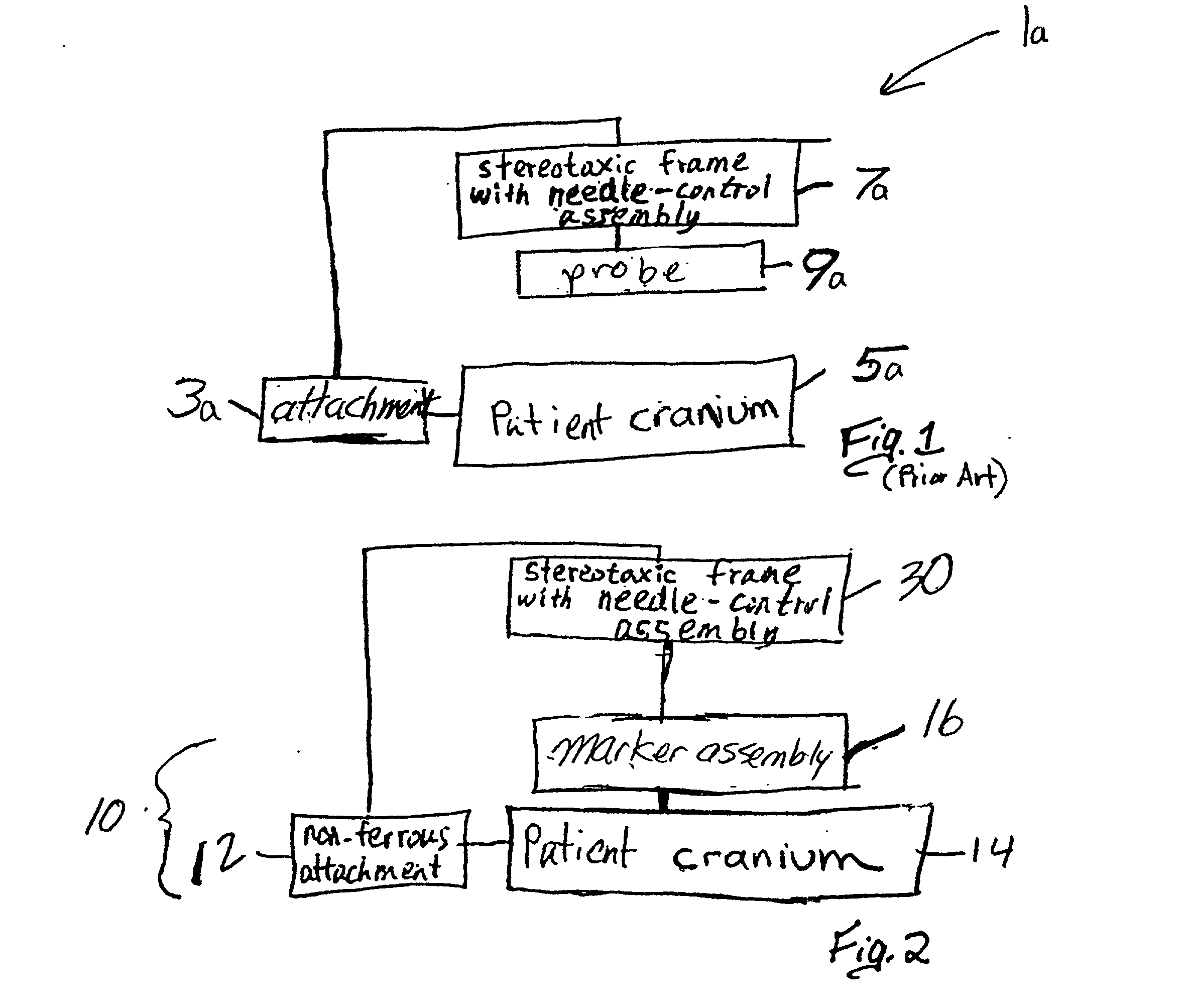
[0022] Referring more particularly to the drawings, FIG. 1 illustrates a block diagram of a prior art apparatus 1a for positioning instrumentation in a cranium 5a of a patient. Particularly, in conventional stereotaxic surgical techniques, an attachment 3a is secured to the cranium 5a and a conventional locator device 7a is connected to the attachment 3a. A probe 9a is positioned above the cranium 5a and directed into an intra-cranial region of the cranium 5a, based on predetermined coordinates derived from earlier diagnostic analysis for example. The predetermined coordinates generally represent an approximation of a target location within the brain, for example, an area of brain tissue to be treated. Prior art analytical and medical instrumentation and procedures, which are suitable for stereotaxic surgery, are well known and for the sake of simplicity will not be detailed further herein.

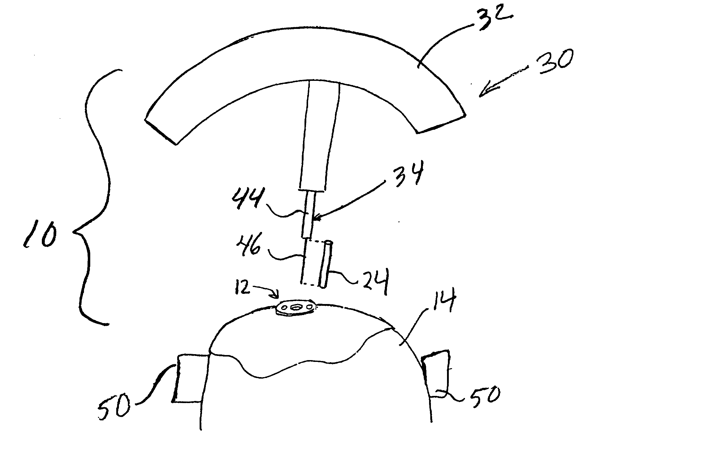
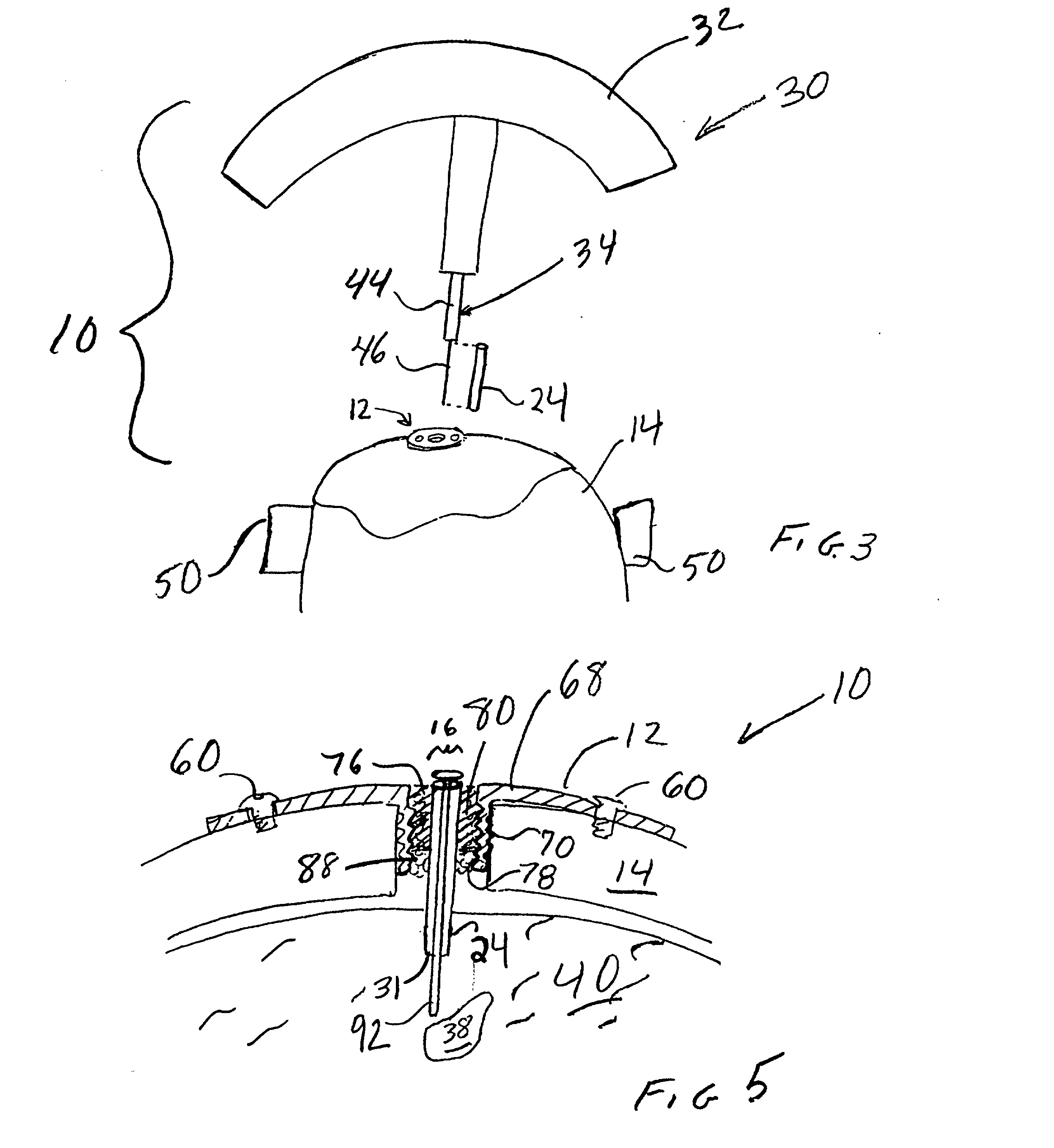
[0023] A simplified block diagram of an apparatus 10 in accordance with the present invention,...


PUM


Abstract

An apparatus for positioning instrumentation into a target region of a brain generally includes an attachment member, specifically a disc adapted to be secured to a cranium, and a marker assembly adapted to be connected to a locator device, for example a conventional stereotaxic assembly. The marker assembly includes a detachable cannula, and is further adapted to be secured to the attachment member in order to immobilize the cannula at a precise position in the brain, thus facilitating additional imaging of the patient in order to determine the position of the cannula with respect to the target region.

Description

[0001] 1. Field of the Invention[0002] The present invention relates generally to a stereotaxic surgical procedure and more specifically to a stereotaxic surgical procedure for the precise placement of an instrument to a specific target region in the brain.[0003] 2. Description of Related Art[0004] Stereotaxic surgery has conventionally been the primary method for the precise placement of instruments to specific targets within the human brain. Despite its widespread use especially in the treatment of Parkinson's Disease, a certain margin of error in localization exists. This error may vary, for example, from 1 mm to 5 mm. Therefore, when precise localization is required, refinement of existing technology may be desired.[0005] The present invention provides an apparatus and method for more accurately positioning instrumentation in a brain of a patient. The apparatus is straightforward in design and construction and can be used with existing technology without requiring a substantial ...

Claims


Application Information

Patent Timeline
Patent Type & Authority Applications(United States)
IPC IPC(8): A61B19/00
CPCA61B19/201A61B2019/208A61B2090/103A61B90/11
Inventor AMIS, JAMES PETER
Owner CYTORI THERAPEUTICS INC
Why Eureka
Try Eureka